The IET is carrying out some important updates between 17-30 April and all of our websites will be view only. For more information, read this Announcement

This discussion is locked.
You cannot post a reply to this discussion. If you have a question start a new discussion

Bonding both sides of an swa cable

Is it necessary to bond both sides of an armoured cable if it’s not being used as a CPC and if you bond it at the supply side of an electrical motor starter panel is there anything in the regs where it should be bonded too or can it just be bolted to the chassis stud using a 6mm fly lead off the gland. 


thanks for your help in advance guys.
  • Thank you Andy. I’ve seen SWA daisy chained with earth links and then using a fly lead of one of them to connect all the armours to the chassis would it be better running individually fly leads to the chassis with the relevant sizes bonding?
  • MrJack96:

    Thank you Andy. I’ve seen SWA daisy chained with earth links and then using a fly lead of one of them to connect all the armours to the chassis would it be better running individually fly leads to the chassis with the relevant sizes bonding? 


    Either individual leads for each gland, or one lead looped or daisy-chained to several glands, are both acceptable in principle.


    In case of the daisy-chain, the fly lead would have to be sized according to the most onerous c.p.c. requirement - so if you had a mix of  small and large cables, it might be easier to have separate leads rather than trying to loop a large conductor onto small glands. Or you might group all the small cables together and have a small fly lead for them, and likewise group all the large cables together, or even link a small gland to a large one with a thin fly lead and the large on to the chassis with a thicker flylead - the possibilities are almost endless.


    If it was the kind of situation where there are likely to be lot of future alterations or modifications, having separate flyleads might make life easier as one cable could then be altered or removed without having to interfere with the connections to others; on the other hand if you had lots of cables terminating but a limited facility to connect to the chassis, then daisy-chaining might be far more sensible.


    If you were confident of the connection between gland and gland-plate, but not of the screws that held the gland-plate to the chassis, you might have only one fly-lead for the entire plate.


    Note that the connections to cable armours are normally a matter of earthing (connecting to a c.p.c.), rather than bonding. Strictly speaking only extraneous-conductive-parts (e.g. water or gas pipes) are bonded. That's significant because the minimum required sizes of c.p.c.s and bonding conductors (including fly-leads) have to be calculated in quite different ways. It's unlikely that any single size (e.g. 6mm²) will be suitable in all cases. Occasionally you might find that c.p.c. is also used as a bonding conductor (say the cable feeds a remote DB where main bonding connections are taken from) - in which case the sizes would have to be large enough to satisfy both the earthing and bonding requirements.


        - Andy.

  • e15b33d89f24807165c20d1d71628d1e-original-500dcc78-7c6c-40c9-b7eb-338ac5143f32.jpg
    Caption

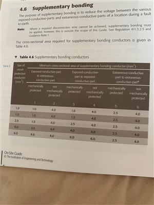
    Thank you for your help Andy. Table 4.6 in the on site guide should give me the size of the bonding conductor. I believe the biggest conductor run to the panel it 6mm so it states 6mm for exposed conductive part to extraneous. Would I be right in thinking this ?
  • Paul Skyrme:

    Potentially if this is feeding a motor of a machine then BS 7671 is irrelevant. (110.2,xi)

    If this is on a VSD, then the SWA will be probably useless as a screen.

    Most we have tested are worse than un-screened.

    Many drive OEM's forbid SWA to the motor for this very reason.


    I'm interested by this. Are the tests comparing unscreened cable (with one core for earthing) with a similar length of SWA where both ends are bonded to metallic enclosures in the thorough way that Graham mentioned? What does the test measure? Do OEMs recommend e.g. a tightly-woven screen instead, to avoid the thin gaps between armour wires?


  • MrJack96, why do you keep referring to "bonding"?


    If I understand the situation correctly, you have a length of SWA which connects a panel to a motor. Both the panel and the motor have exposed conductive parts.


    Odd though it may seem to a lay person, the armour is not just providing mechanical protection so it must have a sound connexion to an earthing point at the supply end (i.e. within the panel) so that ADS may function correctly if the armour (and a live conductor) is pierced.


    The exposed conductive parts of the motor need to be earthed. In this instance, a core of the SWA has been used (properly identified of course) as the CPC. The armour wires could have been used instead. Although it would be good practice to make off the SWA into a gland so that the armour is connected to the motor, this is not essential because the motor already has a CPC.


    Whether banjos, piranha nuts, and fly leads are required to make sound connexions is another matter entirely. There have been numerous threads about this in the past.
  • "the armour is not just providing mechanical protection " if it is actually providing mechanical protection in all circumstances - ref Prof BOD and his small dia drill bit scenario
  • Why’s it not classed as bonding sorry I’m just confused. I know if I used the armour as a cpc it would be earthing
  • Why’s it not classed as bonding sorry I’m just confused. I know if I used the armour as a cpc it would be earthing

    The armour would be classed as an exposed-conductive-part (just like the metal case of a class I appliance) - so the protective conductor connecting it to the means of Earthing would be a c.p.c - since it may have to carry the full earth fault current until the protective device opened to provide ADS. That would still be the case if the armour didn't form the c.p.c. for the downstream circuit as there could still be earth faults either within the cable (if damaged) or at the far end (say to the gland if it wasn't separately earthed at the far end).


    Supplementary bonding is a different kettle of fish where you're connecting together exposed-conductive-parts that are already connected to their appropriate c.p.c.s or extraneous-conductive-parts (which if entering from outside of the installation would already be main bonded) - so even in the worst case they'd only be carrying a portion of the earth fault current as they're in parallel with the appropriate c.p.c.. The idea of supplementary bonding is to reduce the voltage difference between simultaneously accessible parts within a small area (such as a bathroom) - not to provide basic earthing to any one part.


    As you've noticed that OSG table only works for situations where the associated c.p.c. is 6mm² or less - other situations (e.g. larger cables) might well demand larger supplementary bonding conductors. In general when connecting two exposed-conductive-parts the supplementary bonding conductor would have to be at least the same size as the smaller of the c.p.c.s (always subject to the 4mm² or 2.5mm² minimums for any separate protective conductor for mechanical robustness reasons).


       - Andy.
  • Thanks guys. So there is a requirement on sizing the earth links to the required size to carry fault current. As I’ve only really seen armoured coming into the gland plate and it’s mostly always daisy chained with 6mm2 cable. I don’t know if there’s any tables I can use. Thanks again guys.
  • MrJack96:

    Thanks guys. So there is a requirement on sizing the earth links to the required size to carry fault current. As I’ve only really seen armoured coming into the gland plate and it’s mostly always daisy chained with 6mm2 cable. I don’t know if there’s any tables I can use. Thanks again guys. 


    Odd terminology again ("earth links") but see 543.1.1