This discussion is locked.
You cannot post a reply to this discussion. If you have a question start a new discussion

Zs, to test or calculate?

A large contractor working on our site have told me yesterday that it is their policy not to live test final circuits where they cannot use a plug? In order to reduce risk, they will now only calculate Zs, on circuits where they would have to open an enclosure, such as FCU's and light fittings.
The control measures we insist are in place, are IP2X equipment, GS38 leads, two man rule with second man having resus training, among others. So I feel the risk has been reduced to as low as reasonably practicable. An d my instinct tells me that a measured Zs reading must be more accurate than a calculated one, since it will include all parallel paths under test.
The contractor is happy to live test distribution circuits, so it seems they want to pick and choose.
They also state that this is how things are now, and have worked at many different sites, Cross Rail, Heathrow, various MOD sites etc, and that they al accept this as common practice.

I like some opinions to find out what's going on out there on other sites. 
  • For circuits below say about 63 A, we don't worry about the reactance of the cable - see tables at the back of BS 7671. Most of the reactance is in the external loop, and that's why we would normally measure at least Ze or ZDB.


    Appendix 14 of BS 7671 advises that, under many circumstances, measurement prospective fault current in domestic installations is not necessary.


    For larger circuits, I agree there's perhaps something missing, but it's worth remembering that, due to potentially larger prospective fault currents / lower loop impedances, and especially where you are close to the transformer, the loop impedance or prospective fault current measurement itself may be inaccurate. For larger loads, and even final circuit disboards, there is no reason at all why a test socket-outlet specifically for prospective fault current and loop impedance measurement, with suitable backup protection could not be provided, just below the DB or built into MCCs etc. - this is part of the CDM process.


    Don't forget that Appendix 14 of BS 7671 advises that fused leads alone may not provide protection if backup protection at the point of measurement is not present.
  • As far as I know, the reactive component of impedance is not measured by a loop “impedance” tester anyway. Further, the accuracy is always questionable for various reasons. Having that margin of 0.8 Zs7671 as a maximum test value perhaps addresses most issues. A loop impedance on the wrong side of an mcb is worse than a fuse.
  • I am not convinced that the loop test does not measure impedance. Yes, the current used is DC but, as I understand it, a very short pulse is used so inductive effects should be measured too.

    I have also had great difficulty measuring the earth loop impedance of a main incomer, say 400A, because the dip in voltage caused by the brief current pulse was so small that it was masked by the normal spikes on a supply. I tried averaging several successive readings but as some of these were negative, I didn't trust the results. 

    I suspect that, to get a proper result, I needed a much beefier bit of test kit, the sort that would take 2 people to carry it.
  • A loop impedance test of the kind that uses the  50Hz AC supply and switches in a load and looks at the voltage drop will necessarily include all the same impedances, both real and imaginary, that  will appear in a real fault, as that too uses the AC supply.

    The accuracy problem is because   the test current is much lower than a likely fault current  (on a TN system anyway) the voltage drop caused during the test is fractions of a volt, and  if the mains is a bit bouncy for other reasons, as it often is if the supply is shared with loads that are switching, then the meter may mistake some of that voltage drop for the result of its own test load, so the results can be a bit 'fruit machine'.

      By keying the test load in and out in a psuedo-random sequence, and then looking at the average voltage droop and rise for each short part of that test, it is possible to cancel out and mitigate this noise problem, at least to a degree. Also when you are looking at PSSC of kA, then every milliohm starts to count, and the condition of test leads and their connectors starts to be a significant part of the reading, and beyond a certain point 'normal' meter  probes are not really good enough.


    Also I  have seen the effects of RCD cores that look inductive for small currents, but for  large fault would saturate and not current limit, give an over pessimistic impedance on a very low current (no trip) test. The clue is the Zs readings before and after the RCD are far more different than the DC resistance of the contacts would suggest. Still only tens of milliohms of change, but in some cases that may be misinterpreted as the difference between additional work needed, and not.
  • It seems that nowadays it is acceptable across the board to calculate Zs.

    As an aside, I don't think of adding dead R1+R2 results to Ze as being the calculation approach - it's still all based on measurement even if done in parts. For me, calculation would be something like working out the impedance based on the cable length and tabulated resistance per metre - which might have been the approach in the old days when earth continuity would be verified with nothing more than a set of test lamps.

       - Andy.
  • I know an electrician, now retired, who didn’t have his NICEIC renewal signed of by his assessor around fifteen years ago after a few clashes.


    One clash was when his assessor suggested he bought a non-trip loop tester to get more accurate loop test results on RCD protected circuits and he replied saying he had a pencil.


    On a personal note I still have my original Robin multifunction installation tester, the main reason I “upgraded” by buying a Megger non-trip loop tester to accompany it was the increasing number of RCDs being installed, now it seems all these years later I could have stuck with the Robin and a pencil.


     Andy Betteridge
  • Pencils can be truly wonderfull things ?
  • mapj1:

    A loop impedance test of the kind that uses the  50Hz AC supply and switches in a load and looks at the voltage drop will necessarily include all the same impedances, both real and imaginary, that  will appear in a real fault, as that too uses the AC supply.


    But how is that possible? The reactive component of voltage drop in the circuit being measured cannot be determined from an arithmetic subtraction of the voltage drop of the instrument test resistor from the supply voltage. As far as I understand it my MFT places a 59 ohm resistor as a dummy load, tries to establish the volt drop across it over a couple of half cycles and then determines the circuit “impedance” from the voltage difference between that and the supply voltage. Where the reactive component is pronounced surely that is not possible as the VD across the reactance is in quadrature.
  • That's true (lyledunn).  A method that compares voltage magnitudes with and without a resistive load (where that load impedance is many times the source impedance, e.g. to take 20 A) is very insensitive to reactance in the source - it practically doesn't see it at all. 


    One can make inferences based on curve fitting for a range of resistive loads, but that's more for amusement than practical ... I've tried it a few times. 


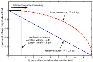
    The following plot was my attempt some years ago to illustrate the relation between current and voltage when a varied resistive load (conductance increasing from open-circuit to short-circuit) is connected to a source with either purely resistive (blue) or purely reactive (red) impedance, or to a current-limited power-electronic source.

    - With the resistive source and load the gradient is a nice straight line as with dc circuits, so any measurement that varies the load between (say) zero and 20 A in a system with 1 kA short-circuit current would make a good estimate of the short-circuit current. 

    - But with the reactive source and resistive load the estimate based on this same pair of currents would be a much higher short circuit current than the actual value that's been chosen here to be the same as in the resistive case, because the voltage drop due to mainly resistive current flowing through the reactive source impedance is pretty well in quadrature with the larger source voltage, just as you say. 

    - (And on the other hand, the current-limited inverter could regulate its voltage to look very stiff, and yet provide much lower short-circuit current: it is 'brittle' stiffness!)

    fd25a70f5dda7bc808aecf8919fccae9-original-vi.png


    "In theory", using phasor calculation, one could calculate the source impedance easily for a Thevenin-style source with resistive and/or reactive impedance. But that would require knowing the angle relation between the voltage phasors at the source (assumed constant for the 0 A and 20 A case) and at the measurement point. The simple practical measurements don't have a way to know this, and just measure voltage magnitude. It is possible with analog methods (phase-locked loop) or digital methods (extrapolate a sine-wave for further cycles) to keep a memory of the phase of the source-voltage based on the times when the current isn't being drawn, and to assume this value continues in the few cycles afterwards when the test-current is being drawn. Then one should be able to get a better calculation, although the small change in voltage for a resistive perturbation of a reactive system would still make it more susceptible to noise. Using a test-inductor (or capacitor) as the load instead of a resistor would let the source reactance be measured while largely ignoring the source resistance. Or electronics could synthesise the currents in phase and quadrature. 

    Getting away from phasors, one can take rapid pulses of current such that much of the voltage drop is caused by L*di/dt instead of R*i, as a way to assess inductance (but this is rather dependent on local shunt capacitance). 


    There's a lot that can be done. Some has been in other applications of impedance estimation, such as inverters that use reactive power consumption to avoid excessive voltage rise with active power injection, or distance-relays that look at the L*di/dt rather than phasors.  Installation testers have got cleverer and more digital, but I'm not sure about the current state of art in implementations by the usual manufacturers of today's products.  They tend not to say anything very interesting about the fine details!  One has to test the tester.  


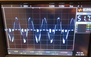
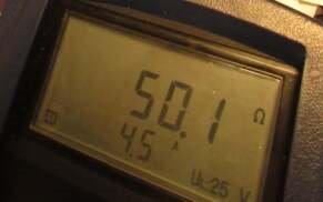
    I don't remember the details of the setup, but the following are from a quick check a few years ago, using an oscilloscope to see what a simple MFT was doing during (I think) a low-current (RCD-friendly) loop test.  It correctly measured the oscilloscope's supposed input resistance, and the oscilloscope showed an interesting waveform that definitely wasn't sinusoidal. 
    593e6f29ddf3a90425f51a19538b83da-original-zest_osc.jpg  35759f8b710f1e4602108c025a5d9f43-original-zest_result.jpg


  • I am not at all sure that this policy is in any way satisfactory. If a qualified electrician cannot safely test any part of a live circuit he is inadequately qualified for the testing job. This is simply a time saving idea, which may well deteriorate to no testing at all, because it is quicker. The proper completely safe procedure is as follows:


    Isolate the circuit. Connect your loop tester using suitable connectors clips or insert the leads into the connector, accessory or whatever live terminal and the other to earth. Energise the circuit. Test Zs and note the reading. Reverse the procedure to disconnect. If anyone can see how this is unsafe I should love to hear.


    You will never find faults by calculation. It is faults we are looking for, loose connections to earth conductors where the sleeving is trapped under the screw etc. One never knows the quality of the workmanship and such are common faults in new installations! Why calculate (presumably that is already done in the design) when a proper test is much better and will find real faults. Multiple paths cover up these faults and ARE NOT SAFE.