Harry Macdonald:
"They also state that this is how things are now, and have worked at many different sites, Cross Rail, Heathrow, various MOD sites etc, and that they all accept this as common practice."
This seems to me to indicate that various, mainly large, organisations are now laying down their own rules which would imply that the methods described in BS7671 are widely seen as unsafe or impractical.
Have we now reached the stage where the BS says one thing but everybody knows that they mean another? If so, that is a very worrying and dangerous state of affairs and exactly what a BS is designed to stop happening.
I hope I am wrong, but with the number of luminaires where you can't easily remove the lamp, switch wire - neutral testing has gone. Live loop impedance seem to have gone, except for sockets, electronics connected to circuits means some don't even do insulation tests.
I hope I am wrong, but I see a dangerous divergence between what the standards say and what electricians now actually do.
BS 7671 does NOT require a loop impedance measurement on every circuit - or in fact, on any circuit!
643.7.3 Earth fault loop impedance
Where protective measures are used which require a knowledge of earth fault loop impedance, the relevant impedances shall be measured, or determined by an alternative method.
Nor does BS 7671 require a measurement of prospective fault current.
643.7.3.201 Prospective fault current
The prospective short-circuit current and prospective earth fault current shall be measured, calculated or determined by another method, at the origin and at other relevant points in the installation.
In fact, according to Appendix 14, in domestic (household) premises where the distributor declares a 16 kA value, you can assume your prospective fault current is 16 kA (although it's likely to be less than this) and not take a measurement at all.
mapj1: That said it does not feel sensible, and there are some potentially dangerous cases, like the total supply reversal, or whole building off-earth that would go un-noticed perhaps for some years until the fault the ADS was meant to prevent occurred, perhaps with fatal consequences.
A fortunate feature for much of the 110 V world (US/Canada - not sure about how the others such as Japan do it) is their use of split-phase. Similarly for countries with 3-phase supply. Then total reversal, i.e. implementing the 'C-S' connection within TN-C-S to the wrong conductor, is a lot harder not to notice, as any swapping of the N with a L/hot would cause the wrong voltage to some of the equipment.

Paul Brewerton:
An d my instinct tells me that a measured Zs reading must be more accurate than a calculated one, since it will include all parallel paths under test.
Hello Paul,
The main problem to compare results of testing Zs and calculating Zs (and their respective SC-currents) is temperature of conductors. The temperature of conductors directly affects the test results (real temperatures at the moment of the test) or the calculation results (theoretically given temperature or temperature defined by standards).
SC-current calculation.
Calculation is needed to obtain the theoretical values of the largest and smallest SC-currents. According to IEC60909 the calculations of the maximum SC-current and the minimum SC-current shall be performed for each checked point.
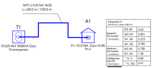
For example the MeteorSPEC software gives the following results for 3-phase Cu 50mm2 cable L=100m and for transformer 400kVA D/Y:
Maximum 1-phase SC-current (temperature of conductors 90C) = 2.213 kA
Minimum 1-phase SC-current (temperature of conductors 20C) = 1.46 kA (a fragment of the calculation report is shown at the end).
SC-current test.
In common case you don’t know the temperature of conductors at the moment of the test. Usually the tested circuit consists from many cable sections that are installed differently and were loaded differently before performing the test.
You get some result, but you can’t say anything - can the SC-current be in this place at another time more or less than what you measured now.
Test versus calculation
Testing and calculation results cannot be directly compared. Calculation gives the theoretical possible boundary. Test results can confirm or not confirm the calculation results, nothing more.
Thus, for the correct selection of the protective device, it is necessary to calculate the SC currents at the end points (usually enough minimum current) of a feeder and obtain the results of tests (which should be greater than the calculated minimum currents).
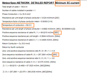
MeteorSpec-NETWORK DETAILED REPORT Minimum SC-current
Total length of cable = 100.0 m
Number of cables installed in parallel = 1
Phase Conductors = Cu 35.0 mm2
Resistance per unit length of phase conductor = 0.524 mOhm/m [20C]
Temperature factor of phase conductor metal = 0.00393 [1/.K]
Temperature of conductors = 90.0 C
Resistance per unit length of phase conductor = 0.6682 mOhm/m, [90C], IEC60909-0 [32]
Positive-sequence resistance of cable R ( 1 ) = 66.8215 mOhm, [90C]
Positive-sequence reactance per unit length = 0.0844 mOhm/m, [50Hz]
Positive-sequence reactance of cable X ( 1 ) = 8.4408 mOhm, [50Hz]
Return Conductor = Cu 35.0 mm2
Return by fourth conductor
Zero- and positive-sequence resistance ratio R ( 0 ) /R ( 1 ) = 4.0
Zero-sequence resistance of cable R ( 0 ) = 267.2861 mOhm, [90C]
Zero- and positive-sequence reactance ratio X ( 0 ) /X ( 1 ) = 3.8
Zero-sequence reactance of cable X ( 0 ) = 32.075 mOhm, [50Hz]
Z ( 1 ) = 66.8215 + j8.4408 = 67.3525 mOhm, [90C][50Hz]
The temperature of conductors directly affects the test results
Maximum 1-phase SC-current (temperature of conductors 90C) = 2.213 kA
Minimum 1-phase SC-current (temperature of conductors 20C) = 1.46 kA
Test results can confirm or not confirm the calculation results, nothing more.

That's odd - I would have expected that conductors at 90°C to have a higher resistance than those at 20°C and hence to have a lower fault current.

We're about to take you to the IET registration website. Don't worry though, you'll be sent straight back to the community after completing the registration.
Continue to the IET registration site