This discussion is locked.
You cannot post a reply to this discussion. If you have a question start a new discussion

Insulation Resistance Measurements

Former Community Member
Hello,


We have a Insulation Resistance measurement unit from Hioki - ST5520.

We are using this to measure multiple devices controlled through a relay matrix as shown in the figure. The positive and negative terminals of the ST5520 is multiplexed through the relay matrix to the 64 pins of the connector. There are 7 pcb's each containing 20 relays.

The individual board testing from ST5520 to the connector is giving a open condition result with a high value of insulation resistance of 9.90Gohm @1000V, when there is no load at the connector output, it is left open.

But the when the whole system is wired and tested with the 7 pcb's(all 32 channels), the value fluctuates and starts with a value from 100Mohm and eventually reaches open condition value.

Is there a problem with this process of multiple channel testing? or this is the expected behaviour? the open condition value(9.90Gohm@1000V) is maintained once it reaches this value and further tests result in this same value. 

Once the system is left OFF for a period of a day, then the testing is resumed again, the same behaviour of starting from 100Mohm to open condition value repeats. Is this to be expected or i am understanding/ doing something wrong?

Any help with this is much appreciated. Thanks in advance.
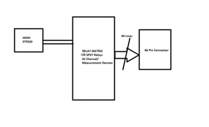
0d3eb1e11f9f4ba9176cae1b22dc1e68-huge-insulation-measurement.png
  • Long story, but I have time on my hands again, so I have been reading various insulation testing related articles and picking up on all sorts of odd things, including the leakage current can be so small the test result can be influenced by the person doing the testing moving due to capacitance.


     https://www.sonel.pl/en/knowledge-centre/press-articles/insulation-resistance-meters/the-influence-of-polarity-of-connected-test-leads-on-the-measurement-results/
  • Former Community Member
    0 Former Community Member
    davezawadi (David Stone):

    A GOhm is 1000 MOhms, a very high resistance indeed. You have a good instrument, but for normal electrical systems, it is rather over the top. I suggest anything over 10 MOhm is taken as a pass if there is no other specification, and you should use the 10 MOhm range, when it will say 9.999 MOhms for effectively greater than this number. If you allow it to auto-range it will take ages to settle on some very high figure which is of no value to you. Come back with the specification value or if you need more info. I would expect this to take a few seconds maximum for each path through the matrix.

    regards

    David CEng Etc.


    Thanks for the reply.


    Will get back to you on the allowed pass value for the transducer.


  • Former Community Member
    0 Former Community Member
    Sparkingchip:

    It was easy to get the tester to display 200 Gohm, I didn't plug the leads in.


    Thanks for the reply.


    This was also what we observed., as in the max overflow value displayed. We also observed this when probes are connected and left open.

    Further when the number of pcb's was around the 4-5 in the matrix, we observed that the ramp up time was in 5-10 seconds, but further increase in the pcb's(even 1 extra pcb) in the matrix increased the ramp up value rather drastically to several minutes, can this be explained completely by dielectric absorption is one of my queries?


  • davezawadi (David Stone):

    If you allow it to auto-range it will take ages to settle on some very high figure which is of no value to you. 


    You have to decide if you are go/no go testing, where you set the parameters and the green light comes on or that when you exceed your minimum requirement everything is okay, so you sign the item under test as safe or if you want to keep a record of readings as part of a maintenance regime to detect deterioration of the insulation, for which you need a accurate test result to know what the starting point was.


    Someone who scribbles the infinity symbol or writes OL in the test result box on a certificate is not being particularly helpful if you don’t know what the upper limit of the range is on their test meter if you are trying to determine the rate of deterioration at a later time.


     Andy Betteridge 


  • The tester being used is a go/no go tester with a green light intended for a production line, it’s not a piece of equipment that seems particularly suited to diagnostic work. 


    Andy B.
  • Putting the question in reverse, how much resistance can be added in shunt with the PCB being tested before it fails to perform the desired function ? - it may be worth trying to set the fail limit to 5 or ten times that, rather than looking for the highest the meter can detect,  assuming  the answer is not gigohms, in which case the finished product will need a lot of environmental protection.

    Be aware that the meter will internally be configured to cancel the effects it's own current drawn as best it can, and it does not mean the meter has internal resistance as high as it can measure - there are lots of tricks with instrument design that are used to get the optimum sensitivity.