This discussion is locked.
You cannot post a reply to this discussion. If you have a question start a new discussion

Insulation Resistance Measurements

Former Community Member
Hello,


We have a Insulation Resistance measurement unit from Hioki - ST5520.

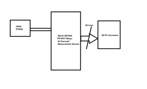
We are using this to measure multiple devices controlled through a relay matrix as shown in the figure. The positive and negative terminals of the ST5520 is multiplexed through the relay matrix to the 64 pins of the connector. There are 7 pcb's each containing 20 relays.

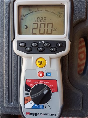
The individual board testing from ST5520 to the connector is giving a open condition result with a high value of insulation resistance of 9.90Gohm @1000V, when there is no load at the connector output, it is left open.

But the when the whole system is wired and tested with the 7 pcb's(all 32 channels), the value fluctuates and starts with a value from 100Mohm and eventually reaches open condition value.

Is there a problem with this process of multiple channel testing? or this is the expected behaviour? the open condition value(9.90Gohm@1000V) is maintained once it reaches this value and further tests result in this same value. 

Once the system is left OFF for a period of a day, then the testing is resumed again, the same behaviour of starting from 100Mohm to open condition value repeats. Is this to be expected or i am understanding/ doing something wrong?

Any help with this is much appreciated. Thanks in advance.
0d3eb1e11f9f4ba9176cae1b22dc1e68-huge-insulation-measurement.png
  • PP91:


    Yes, read about "dielectric absorption". So we waited to measure the time taken to reach a high value. But the issue is that the time it is taking to reach a high value is in the range of 10-20mins approx for each channel. This is producing a huge overhead. 


    There is far more I don’t know about this subject than I do, so I have more questions than answers.


    If the insulation test is run for twenty minutes, how long should be allowed for the discharge?


    Andy Betteridge 


  • The reverse effect depends on the mechanism - there may be no stored charge - if it was mostly caused by current flowing to drive off damp then although you put charges through the system to do that, you do not get them back however long you wait, as that is essentially a resistive effect. However, the low resistance will be back in a few hours of days if you do not control the environmental conditions.

    If it is dielectric absorption and recovery (loose but not free charges) then the recovery time is similar to the the charge up time.

    I;d also question how the parts are going to be used after testing - if 100nA really matters, they will pass on the day, but may well fail after a few days in storage.
  • The maximum measurement that this tester can record is 9990 MΩ according to the specification sheet, as I read it the tester does not have a giga ohm range.


  • 100 V ≤ V < 500 V

    500 V ≤ V ≤ 1000V

    TEST LEAD L2200

    70 cm (2.30ft) length, detachable large alligator clips or needle tips are bundled, CAT IV 600V, CAT III 1000V

    Resistance range

    2MΩ 20 MΩ

    200 MΩ

    2MΩ 20 MΩ 200 MΩ

    2000 MΩ

    2MΩ 20 MΩ 200 MΩ

    4000 MΩ

    Max. display

    4.000 MΩ 40.00 MΩ

    999.9 MΩ

    4.000 MΩ 40.00 MΩ 400.0 MΩ

    9990 MΩ

    4.000 MΩ 40.00 MΩ 400.0 MΩ

    9990 MΩ

    Resolution

    0.001 MΩ 0.01 MΩ

    0.1 MΩ

    0.001 MΩ 0.01 MΩ 0.1 MΩ

    1 MΩ*

    0.001 MΩ 0.01 MΩ 0.1 MΩ

    1 MΩ*

    Guaranteed accuracy range

    0.002 MΩ to 2.000 MΩ 1.90 MΩ to 20.00 MΩ 19.0 MΩ to 200.0 MΩ

    200.1 MΩ to 999.9 MΩ 0.002 MΩ to 2.000 MΩ 1.90 MΩ to 20.00 MΩ 19.0 MΩ to 200.0 MΩ 190 MΩ to 2000 MΩ 2010 MΩ to 9990 MΩ 0.002 MΩ to 2.000 MΩ 1.90 MΩ to 20.00 MΩ 19.0 MΩ to 200.0 MΩ 190 MΩ to 4000 MΩ 4010 MΩ to 9990 MΩ

    Accuracy FAST/SLOW

  • A GOhm is 1000 MOhms, a very high resistance indeed. You have a good instrument, but for normal electrical systems, it is rather over the top. I suggest anything over 10 MOhm is taken as a pass if there is no other specification, and you should use the 10 MOhm range, when it will say 9.999 MOhms for effectively greater than this number. If you allow it to auto-range it will take ages to settle on some very high figure which is of no value to you. Come back with the specification value or if you need more info. I would expect this to take a few seconds maximum for each path through the matrix.

    regards

    David CEng Etc.


  • Hands up I was having a moment there, I cannot say I have actually ever worked in giga ohms.


    As I said above I have a tester capable of testing to 200 Gohm, but it's not something that I need to concern myself with. 


    I am reading one of the Megger guide again and it says that OL or whatever is shown as the upper limit of the meters range is not a reading,  merely an indication that the true reading is beyond the capability of the tester. 
    ae89d14b64faa491228d77d47ab05228-original-20200711_175158.jpg
  • Former Community Member
    0 Former Community Member
    mapj1:

    At 1000V you will be seeing all the effects insulation can throw at you in everything, the PCBs,  the relays, perhaps the flux used to solder the PCBs, and any finger prints on the exposed ends of wires -  everything will matter at this level of resistance - to get the best part of 10 gig-ohms, you are asking for  something like 100nA or less to flow, now that  that is a mere 10^12 electrons per second. - what area of insulation are you stressing -  each atom is ~ 250pico metres radius, or if you prefer to think of it as atoms, then each square mm of insulation to live metal interface exposes about  16 million million atoms, it is not reasonable over many hundreds of square mm of contact area between insulation and  live metal not to expect a detectable percentage of the atoms to have either a free electron (steady leakage current ) or a slightly wobbly one (slow polarisation and dielectric recovery)


    If you really do need to measure giga-ohms on the test specimens, then you need to be gapping the insulation to give longest possible creepage paths and large clearances to keep the E field down, cleaning everything till it gleams, baking it to drive of moisture and then encapsulating as much as possible in HV laquer, or alternatively after cleaning and bake off, doing the whole test in vacuum. 

    Can you test at lower voltage ? - if the resistance looks higher , you may also be suffering the onset of corona discharge to the air. This can be tracked down, either using a MW radio, or a UV detector. (or just hopefully polishing off all surfaces that are not smooth - cut wire ends make quite good needle electrodes.)


    But before all that, as others have said, check if you really do need to measure 10 gigohms, or if a lower pass limit can be set - a few million ohms is normally OK for a  a wiring installation, and much easier to handle.


    Thanks for the Reply.


    This gave me some perspective. Thanks for the explanation. I understand some of the things to be taken care of written here and already have been implemented. Since there are many things which affect these high IR values, wanted to get some info which can be improved. Lower voltages(100V) has also been tested, which gives rise to similar issues, the ramp up time is comparatively less here.


  • It was easy to get the tester to display 200 Gohm, I didn't plug the leads in.


  • Former Community Member
    0 Former Community Member
    Sparkingchip:
    PP91:


    Yes, read about "dielectric absorption". So we waited to measure the time taken to reach a high value. But the issue is that the time it is taking to reach a high value is in the range of 10-20mins approx for each channel. This is producing a huge overhead. 


    There is far more I don’t know about this subject than I do, so I have more questions than answers.


    If the insulation test is run for twenty minutes, how long should be allowed for the discharge?


    Andy Betteridge 


    Thanks for the reply.


    For the discharge time, we are following the one mentioned in the megger pdf i.e 4 times the charge time.


  • Former Community Member
    0 Former Community Member
    mapj1:

    The reverse effect depends on the mechanism - there may be no stored charge - if it was mostly caused by current flowing to drive off damp then although you put charges through the system to do that, you do not get them back however long you wait, as that is essentially a resistive effect. However, the low resistance will be back in a few hours of days if you do not control the environmental conditions.

    If it is dielectric absorption and recovery (loose but not free charges) then the recovery time is similar to the the charge up time.

    I;d also question how the parts are going to be used after testing - if 100nA really matters, they will pass on the day, but may well fail after a few days in storage.

    Thanks for the reply.


    The reverse effect was tested. The value goes to low value after reversing the polarities and the ramp up time is almost same.