CCSparkingchip:
Quote:
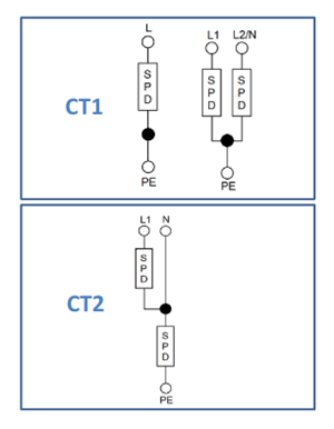
An SPD configuration based on connection type 2 (CT2) is required on a TT earth arrangement if the SPD is upstream of the RCD. The RCD being downstream of the SPD would not operate should the SPD become defective.
I am still thinking about that ?
And with the TT installation you don’t want a SPD that will fail leaving a connection between neutral and earth leaving it as TN-C-S.
We're about to take you to the IET registration website. Don't worry though, you'll be sent straight back to the community after completing the registration.
Continue to the IET registration site


