2. How self regulated tracing cables are inherently safe and can be used in hazardous area?
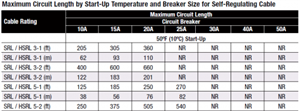
3. How the Maximum circuit length is determined according to the breaker type? What is the equation used here? (see the picture below)

Nick Parker:
1. Why the heat tracing cables draw more current during starting at start up temperature?
2. How self regulated tracing cables are inherently safe and can be used in hazardous area?
3. How the Maximum circuit length is determined according to the breaker type? What is the equation used here? (see the picture below)
EEEEErrrrrmmmmn.
1. Cold = Lower electrical resistance. Hotter = higher resistance. Ohms Law.
2, Dunno. What do you mean by a hazardous area. Car filling station? Gas works?
3. Aren't they rated at so many Watts per meter?
Z.
Andrew Ince:
"Another advantage of PTC heaters in tape form or otherwise, is that they are not sensitive to voltage variations within reason. At a lower line voltage they will draw more current and maintain the same temperature."
Surely the current will reduce at lower line voltage as per Ohms Law.
No, Ohms law is not applicable in this case as the resistance is not fixed but varies substantially. Suppose that a given installation requires say 1,000 watts to maintain the required temperature. At 250 volts that will be 4 amps, and at 200 volts it will be 5 amps.
This is a considerable advantage and simplifies the design, and may save energy.
If instead old style resistance wire heat tape had been used, then it should be designed to absorb 1,000 watts at the lowest likely supply volts, say 200 volts. If the actual supply voltage was 250 volts then the current would be a little over 6 amps, and the loading increased to over 1,500 watts. A waste of over 500 watts.
We're about to take you to the IET registration website. Don't worry though, you'll be sent straight back to the community after completing the registration.
Continue to the IET registration site