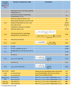
When I look at line 10 (B40 mcb on a 6/2.5 twin and earth,TNS system the max circuit length due to zs is given as 23m(no RCD).Yet when I calc R1 +R2 x 23m I get 10.49x23/1000 = 0.24 ohms.Add ze for TNS to this(0.8) gives 1.04 ohms,whilst table B6 gives a max zs of 0.88 ohms for a B40.Wondered where I,m going wrong.
Regards,
Hz