
There's no stopping me now.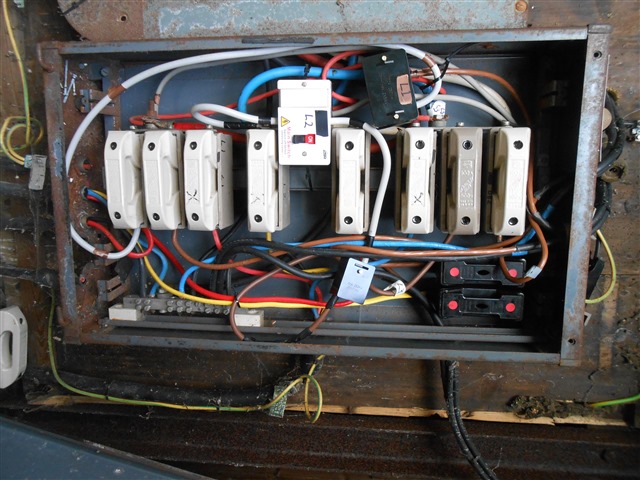
Step one- posting a photo.
Step two- getting the photo the right way up.

The top of the ceramic fuse carrier bases have flat bus-bars that are held by screws onto the fuse bases and internal contacts. Because some of the fuse carriers have suffered from heat/corrosion damage "repairs" have been made. Electrically it is sound and still in full working order.
Z.

No, that's not it. I appreciate that you have seen it in the flesh, but there are at least 3 fastenings, possibly 5 lying on the floor of the box - the side with the hinges. So either gravity has put them there, or somebody is playing games with a magnet.
By my reckoning, the L2 switch should be upright.
Only for you Chris, to solve the mystery I have searched for another photo to put everything into context. You are looking at an antique operational installation. Yes, I know what you are thinking.
But, what is the earthing arrangement?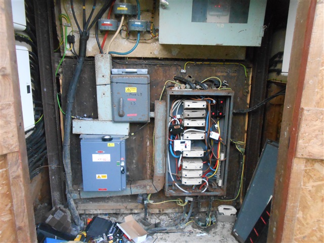
Presenting as TN-S - is this site large enough for a private or at least dedicated transformer so there will not be unexpected changes to Zs and PSSC? The singles running the current transformers look a bit unrestrained and near the edges of that duct with the lid held on by cable tie, so I hope the earth wiring for that is going to win a race with the supply fuse.
Compared the phase conductors all the green/yelllow and some of the black looks a bit thin.
Given all the outbounds seem to be single phases 3 boards might have been expected, or are there some 3 phase sub mains going out ?
Certainly one where you would not start from here nowadays.
Mike.
The incoming is 400 Volt from overheads. There is no dedicated site transformer. The main earthing is provided by a single large conductor running downwards that disappears into a duct with the supply cable. P.N.B? I commented on the current transformer wires many months ago but was told on this forum that they are probably o.k. as they are housed in a locked room.
The three main D.N.O. fuses are rated at 400 Amps each.
All chalets are TT earthed.
Z.
We're about to take you to the IET registration website. Don't worry though, you'll be sent straight back to the community after completing the registration.
Continue to the IET registration site
