This discussion is locked.
You cannot post a reply to this discussion. If you have a question start a new discussion

What earthing arrangement is this and will RCDs operate

Hi, 

I found the below image on an IET forum. 

electrical.theiet.org/.../

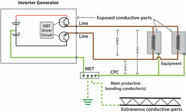
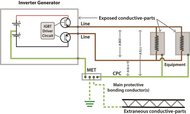
The voltage potential between L&N (well, line and line) is 230V, with the voltage between each of these lines and the CPC sitting at 115V. 

The article states this is a TN-S earthing arrangement if a reference to earth is made using a rod, however I note there is no N-E relay/bond. 

Can anyone confirm this is correct and that this is indeed a TN-S earthing arrangement? 

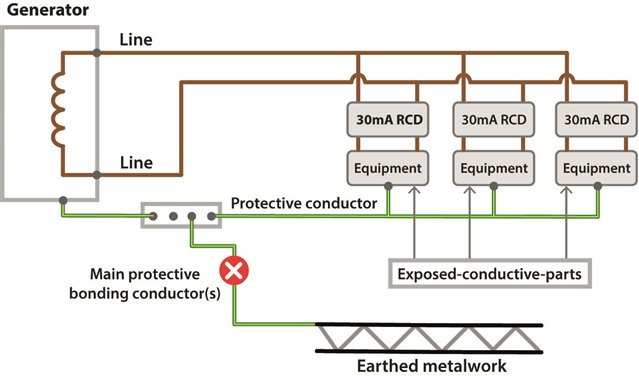
Will RCDs connected to the output of the supply operate correctly, I presume so because current can flow between line(s) and CPC. 

Thanks. 

  • Victron inverter installation instructions 

    www.victronenergy.com/.../GBISM010037000_REV0020030304.pdf

    There doesn’t appear to be an agreement on what constitutes a “Floating earth”

    The previous post with the illustration from the IET article shows a neutral/earth link, whereas Victron says to remove the link to create a floating earth.

  • Despite the caption on Figure 4 I'd not consider that to be floating, at least in the N-E bond sense there is clear continuity, A truly floating system, in my mind at least would be able to pass an insulation test between L+N to E as say a shaver socket would. AKA "IT"

    The other kind of floating with a bond is TN- x without the terra-firma, so NE bond but no electrode or building steels. I'm not sure that figure is the best  example of one of those either. Are the extraneous parts serving as an adventitious  electrode ?

    Mike

  • The Victron inverter with the earth link parked on the dummy terminal is simply “unearthed” from how I am looking at it.

  • Despite the caption on Figure 4 I'd not consider that to be floating

    I agree. Not only does N-PE link rule it out of being a separated or IT system the fact it's connected to an extraneous-conductive-part (by definition, something that has a potential) means it can't be floating. It's more tike the off-planet TN-S systems - e.g. on mobile units.

       -  Andy.

  • Let’s go back to the original illustration, a bit long winded, but I’ll get there.

    If that is in a vehicle such as a lorry horse box with a 24 vDC system for the lorry electrics, a 12 vDC system for the leisure battery and equipment because the fridge and other appliances were made for recreational vehicles such as caravans and motor homes, then you add two 12 vDC batteries for a 24 vDC inverter that could presumably connected to both the 12 vDC and 24 vDC systems, the AC earth connection would be at +12 vDC to the chassis and everything grounded to it; and so would the earthed metalwork of the fridge and the other appliances?

  • Regards my earlier ramble:

    Imagine this scenario.

    New build house with a combi-boiler that has wireless controls, the copper gas pipe does not have a Main Protective Bond because the supply is through a plastic pipe and the heating system has plastic pipework as well.

    The homeowner buys an inverter generator and then disconnects the boiler electric supply flex from the installation and fits a plug to the flex to supply it from the generator.

    The boiler will not run because the flame sensor completes its circuit through the body of the boiler and the earthing system.

    So the home owner fits a neutral/earth link inside the new boiler plug.

    Will the boiler run and if so why, conversely if not why; and will the boiler or generator be damaged doing so?

    My take is that it is an unearthed generator and the Method of Protection is separation, so with this “neutral”/earth link installed the system is running under First Fault conditions, the boiler will run, but there could be 120 volts on the earthed metalwork of the boiler.

    The illustration of the intended intended installation from the IET article could be this one, but with a “neutral”/earth link added, when there isn’t actually a neutral at zero volts, but two live lines at 120 volts with 240 volts between them, so the boiler flame sensor would see 240 volts between the line it is connected to and the boiler chassis.

    Figure 5 Generator configured as electrical separation

  • the AC earth connection would be at +12 vDC to the chassis

    I'd hope that no-one would arrange it like that as any connection between an (a.c.) exposed-conductive-part and the chassis (quite likely for a fridge) would short out one of the batteries. Normally the chassis would be the common 0V reference for all systems.

    The boiler will not run because the flame sensor completes its circuit through the body of the boiler

    Does it rely on the c.p.c and N-PE link though? When that bit failed on my main 24 and I cut apart the epoxy encapsulated unit (just to see if I could see what had gone phut and if I really needed to pay several tens of pounds for a new one next time) as well as a few electronic components, there seemed to be a small transformer - which I presumed generated HV between the electrode with the chassis - so the loop seemed to be contained within the appliance. other makes/models could be quite different of course. Relying on an external N-PE link - feels a bit dodgy to me - how would it work in those parts of the world where the supply may be 220V between two lines?

    but there could be 120 volts on the earthed metalwork of the boiler.

    Depends what you're measuring against. If you earth one pole from the generator then that's normally deemed to be 0V - what used to be the centre point would now be at 120V and the other line at 240V. Of course you wouldn't choose to do that if the centre point of the 'battery' side was also earthed and you didn't have separation between the d.c. and a.c. sides, as, again, you'd end up with a short.

            - Andy.

  •  

    I am old enough to have driven a pickup with a Positive Ground and chrome bumpers, I was taught to keep the bumpers away from those on another vehicle when using jump leads to start it or sparks could fly.

    I know it’s now very rare, but vehicles can be positive earthed and with a First Fault on some wiring systems the vehicle body and chassis could be at a higher voltage without any one getting a shock.

    Hence I am very wary of people making an “earth” connection when there was never intended to be one.

  • but vehicles can be positive earthed and with a First Fault on some wiring systems the vehicle body and chassis could be at a higher voltage without any one getting a shock.

    Ah yes - +ve earth systems can be fun - my parents had a Morris Traveller at one time, and the local garage couldn't figure out why the battery kept going flat - until someone noticed they'd put the battery back in a "conventional" manner - it mostly worked OK, until the battery started to run down and the regulator switched the dynamo in ... which then actively discharged the battery!

    First faults on +ve earth systems should disconnect in just the same was as -ve earth though (creates a short and blows the fuse). Chassis wise both systems are at (conventional) 0V - it's the insulated wiring system that then differs - either +12V or -12V.  In normal circumstances you can touch bumpers without drama. It's the jump leads completing the circuit by connecting -12V to +12V or -12V to 0V or +12V to 0V that causes the issue.

       - Andy.