This discussion is locked.
You cannot post a reply to this discussion. If you have a question start a new discussion

Temporary Connection of Generator to Domestic Distribution System

Hi All,

I recently came across a very interesting article - link below:

https://electrical.theiet.org/wiring-matters/years/2020/82-september-2020/mythbusters-6/

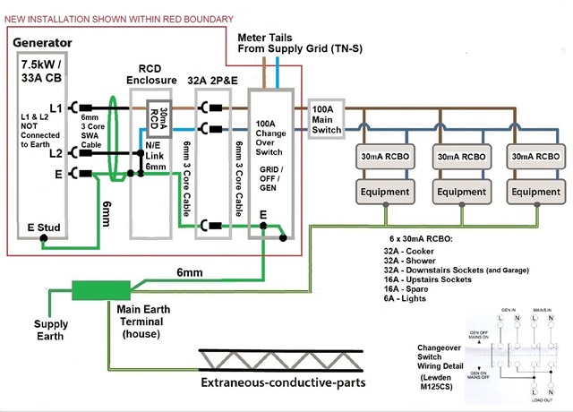
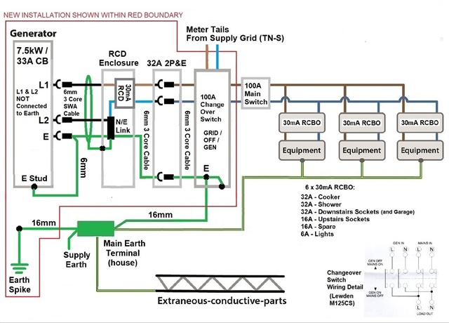
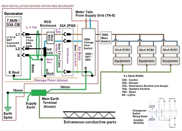
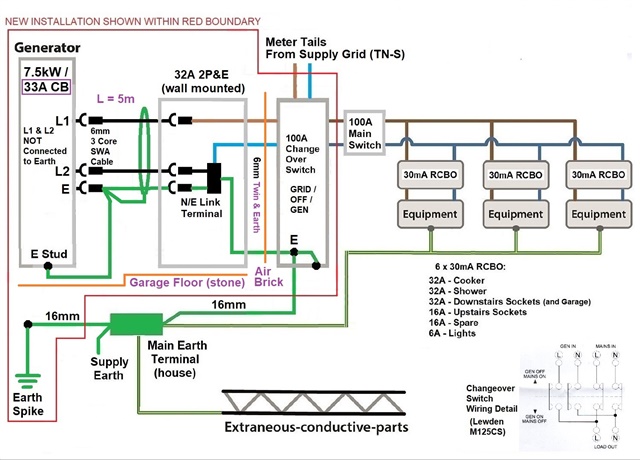
Where I find this article very interesting, is in relation to the requirement / or potentially non-requirement  of an Earth Spike, for the Temporary connection of a Generator to a building (in the article a Site Office is mentioned).

Please refer to the attached rough sketch / scheme for the Temporary Connection of Generator to Domestic Distribution System, which was originally based upon Figure 4 from the linked article - I wonder whether this could be considered, at least in principle, to be an appropriate proposal for the temporary connection of a generator to a domestic premises? In the attached scheme, there is no Earth Spike, and a 30mA RCD is included at the output of the generator, which would be connected to the generator via an appropriately sized SWA Cable. I would consider the potential for some nuisance tripping of the upstream 30mA RCD (in reality, this would be a rare occurrence) to be an acceptable price to pay, for the added protection that it would provide.

I would very much appreciate, if any of you could possibly find a moment or two, in order to share your thoughts in relation to the above / attached.

Thanks,

Harry G.


  • Would be an idea to consider selectivity of RCD's

    From your attached IET mythbuster 

    "The RCD must be set at no more than 100 mA with a time delay of no more than 0.2 seconds; this affords a degree of selectivity with downstream devices (i.e. 30 mA devices on final circuits)."

  • One big difference between your setup and those described in the article, is that your protective conductors remain connected to the DNO's - so if you were to suffer a L-true Earth fault on your system, you'd potentially be raising the DNO's PE/PEN conductor (which may well not be connected to Earth any more due to the fault or maintenance) to a hazardous voltage above True Earth. Your 30mA RCD might provide some shock protection, but there would sill be some risks (RCDs do fail) and would certainly risk upsetting meter readings used by DNO personnel to diagnose faults. I can see the DNO not being at all happy with such an arrangement.

    Attempting to switch the DNO's PE conductor is very difficult to do safely - to avoid the possibility of any simple failure leaving the installation connected but without an Earth, you'd need a pretty sophisticated arrangement whereby the PE contact was closed first, then verified somehow, before the L & N contacts could be closed, then in the reverse process, likely you'd want to verify that the L contact has indeed opened before opening PE.

    Legally, the ESQCR demand that any installation that has on-site generation, even switched alternative, meets BS 7671, and the general requirements of BS 7671 for generators demand a local means of Earthing. So while alternatives like "IN-S" might exist for some section 7 special locations (mobile units, construction sites etc), you'd be on a sticky wicket applying them to a simple (or in some ways more complicated) domestic installation.

       - Andy.

  • I would very much appreciate, if any of you could possibly find a moment or two, in order to share your thoughts in relation to the above / attached.

    Regulation 551.4.3.2.1 would require an additional earth electrode  for TN supplies (unless the installation is supplied from a private HV-LV transformer). This Earth electrode could be connected at the MET, or at the generator.. For TN systems, an additional earth electrode at the MET is recommended now anyway (and notes to this effect have been in BS 7671 for many a long year) - so perhaps best at the MET.

  • Hi Graham,

    Thanks for your informative reply.

    In light of your comments, I have revised my proposal - I am thinking that the attached updated proposal sketch / scheme should now
    be in keeping with accepted practices / compliant with the regulations, for a domestic premises, with TN Supply?

    Best Regards,

    Mark G.


  • Hi Andy,

    Thanks for your informative reply.

    In light of your comments, I have revised my proposal - I am thinking that the attached updated proposal sketch / scheme should now
    be in keeping with accepted practices / compliant with the regulations, for a domestic premises, with TN Supply?

    Best Regards,

    Mark G.

  • That second sketch looks just the ticket and works for any supply earthing type- the electrode need not be a rod, if there is foundation piling or steelworks known to be in contact with the ground, go for it, but you would still need to test it like an electrode. 
    The new RCD can be a 100mA and with a 0.1s time delay  ('S' type) if you prefer to avoid one-out all-out tripping. This does limit the permitted installation methods a bit though, to surface wiring or things that are armoured or deep below the surface - no T and E or arctic flex under 5mm of polyfilla without a 30mA RCD!  I'm sure you would not, but I'm aware that others may read this website for inspiration.

    Mike.

  • The SWA before the generator's RCD looks a little odd to me - usually SWA is chosen because of risk of mechanical damage and the usual mechanism is to earth the armour and use ADS to provide shock protection. It's not usual to rely on the SWA as mechanical protection alone.  In this case there are no conventional protective devices to provide ADS, so at best you'd be relying on stalling the generator (or at the very least hoping that the generator voltage output would collapse) due to the fault and the N-PE link at the far end of the SWA forming a short circuit. All of which may well happen in the real world, but without some specific data about both the cable and generator, it's difficult to prove.

    I would think a  more robust approach would be to site the RCD as close as reasonably practical to the generator and use a Class II (double/reinforced insulation) approach between the two - say insulated & sheathed singles in insulating conduit. All depending on the actual conditions of course. You could then use SWA after the RCD if you wish (to the socket or change-over switch).

    But yes, permanent attachment of a local electrode to the MET brings it all in line with usual practice. BS 7430 I think still recommends it has a maximum resistance to Earth of 20Ω, but that can be reasonably difficult to achieve and as long as you're not supplying any TT installations (e.g. outbuildings with their own separate earthing facilities) significantly high higher values are likely to be perfectly adequate in practice.

        - Andy.

  • Nothing to do with the original question, but what software have you used for your "rough sketch" please?

  • Hi Andy,

    Thanks for the extra points for consideration.

    I have attached an annotated scheme here, which shows the 'nitty gritty' details of the installation, and may give some idea as regards the reasoning for my proposing SWA Cable upstream of the RCD (there is a 33A Circuit Breaker built into the generator - not sure of the precise trip characteristics). Possibly, it may be better to go with your suggestion of double insulated wiring upstream of the RCD - the reason that I had not done this, was I suppose, mainly relating to the increased mechanical robustness of the SWA Cable and Metal Enclosure for the RCD. 

    Also, I have attached a more simple scheme, without an RCD - I would say that in this case the SWA Cable between the Generator and Wall Mounted 32A Connector becomes a critical requirement?

    I'd be interested to receive your thoughts in relation to the above / attached.

    Best Regards,

    Mark G

    .

  • Hi Mike,

    Thanks for your informative reply.

    I have attached an annotated scheme here, which shows the 'nitty gritty' details of the installation.

    Also, I have attached here a more simple scheme, without an RCD - I would say that in this case the SWA Cable between the Generator and Wall Mounted 32A Connector becomes a critical requirement?

    I'd be interested to receive your thoughts in relation to the above / attached.

    Best Regards,

    Mark G