Cable Sizing based on I2T - 5 second boundary

In order to size a load carrying conductor after a circuit breaker, I've historically included an I2t calculation to ensure the cable used has a sufficient cross-sectional area in the event of a fault, to ensure the insulation doesn't damage.

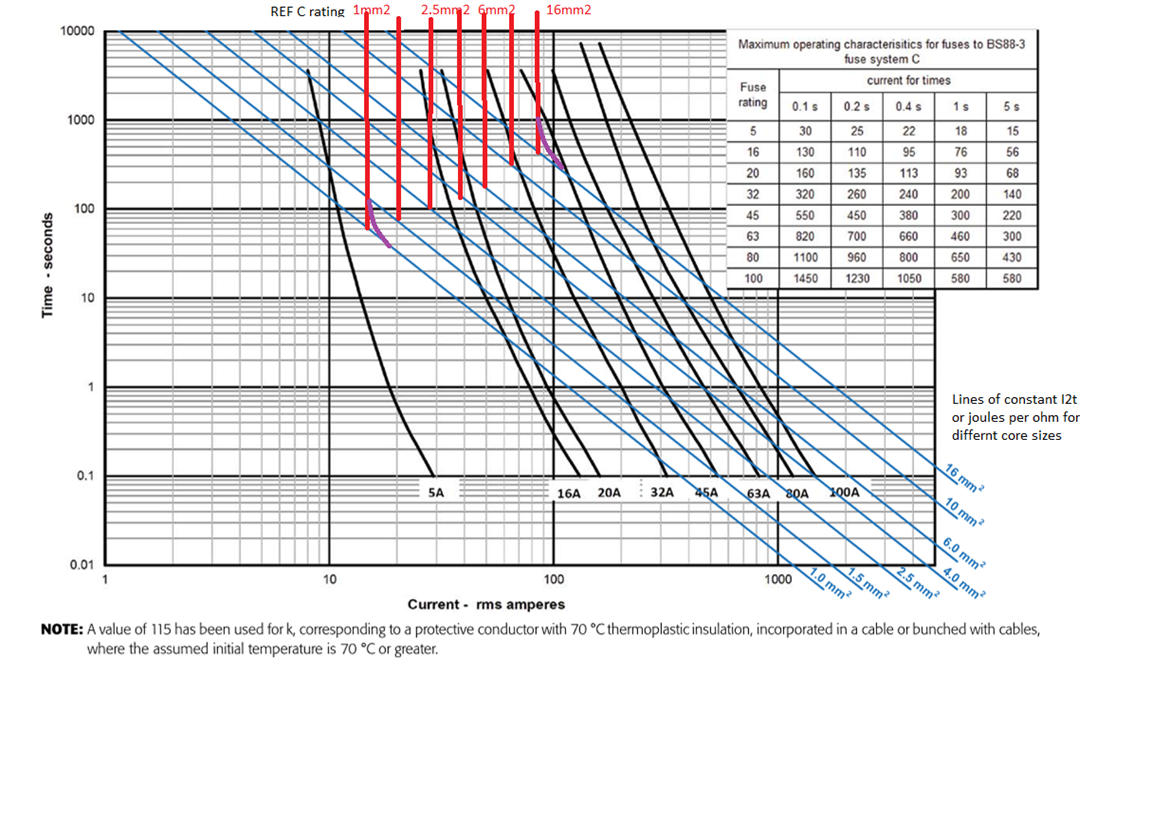
To do this, I use the Time-Current Curve available for the breaker to calculate the worst case A2s. ( Fault Current^2 (A) x Trip Time (s) )

The Time Current curve for the part model I use shows the curve flattening at 1000s - this has historically been where I've calculated the worst case A2s.

I've recently been reading on the subject and talking to other Engineers, and I've been told that for trip times beyond 5s, the Adiabatic equation isn't really applicable.

Beyond that, if you plot a bell curve of Fault Duration against its likelihood to occur, then using a boundary of 5s would likely cover up to the 95th percentile of possible faults - which offers a good balance between safety, reliability and cost.

If the adiabatic equation is no longer applicable beyond 5s, then I obviously need to find a more appropriate way to calculate it - however I'm not convinced that a 5s boundary would cover the 95th percentile of possible faults.

Is the reasoning sound here? If so, does anyone know where this is possibly stated, to offer reasoning behind the decision?

If it is true; the 95-100th percentile of faults could cause a fire in the absolute worst case scenario, so how do you quantify the risks with that?

If not, should I be calculating up to the boundaries that the manufacturer tested for (i.e. 1000s), or is there a better argument for a lower value such as 5s?

If I've misunderstood the subject here, your help would be appreciated.

  • Adiabatic, means no time for heat to escape to the surroundings - such as during a very fast event.

    so the temperature rise is set only by the energy dissipated - current times volts times time, and the thermal heat capacity proportional to mass, of the cable itself. But of course the cable does not carry on getting hotter, as it reaches an equilibrium after some time, when the heat soaking out of the cable into the air or building fabric  matches that heat generated within it. Then the question is, now it has stopped rising, is the equilibrium temperature actually acceptable.

    Clearly 1000seconds, which is long enough for me  to take a shower, get dried and dressed  and walk to the pub and be well down the first pint, is not really 'instant'. *  But that begs the question what  is. Plots rather like this

     Adiabatic plots 

     illustrate that - I think you may also find reading that thread helpful.

    The short  answer is it depends on the cable size of course.

    Mike.

    * I am quite quick in the shower and the pub is just round the corner from my house, I appreciate not everyone has this luxury and the sub kilosecond pint may not be a realsitic  option for everyone.

  • BS 7454 (which is actually referenced in BS 7671) has a non-adiabatic approach that should be used.

    The limitations to adiabatic were discussed recently in another thread: Adiabatic plots

    I see Mike has already directed you there.

  • This makes more sense to me, thank you for the clear explanation.

    If I calculate my own value of 'k', is there a way of calculating how long it takes a given CSA to reach that equilibrium point? Basically doing my own adiabatic plot.

  • Thank you, I'll try and get a copy of 7454.

    Thanks again

  • the problem  is that while the rate heat arrives is easily calculated , power times time - so resistance times I squared t if you like,  the rate it leaves is a function of the cables environment, generally the more conductive that is the faster things reach a steady state, and the higher current the cable can take. In extremis would be cables immersed in flowing cold water where 1mm2 singles may be good for 60 amps all day, and equilibrium is a fraction of a second, but that is not a standard installation method ;-) in that case it is the thickness of plastic that sets the stabilisation time as the water is isothermal.


    to  first go, take the I2t from the adiabtic calc and lay it on the graph of time and curernt, as per that thread I linked to.
    like this It2 in blue, steady state ratings vertical lines in red (here for T and E method C but only because I can remember those figures more or less - do not design using this graph it is an educational aid only.)

    For any given cable size the adiabatic - blue line, for fast stuff, and the red line - steady state long term rating for that installation method, define a safe operating area -below or to left of line is safe. high and right may damage the insulation.  Note that for clipped direct, assuming 5 seconds is some way from from cable damage, and the equilibrium time, where blue and red meet for a given cable is not constant,  but then 1000 seconds is not on the blue curve at all though maybe for something like a 50mm2 cable  it would be.

    Note how the intercepts are on a more or less straight line and the time rises very roughly in lockstep with area - a 10mm2 cable needs more like 8 times than 10 times longer to reach equilibrium than a 1mm2 one.

    Mike.

  • Where the fault currents gets so low it takes that long to disconnect, then the situation is more like an overload than a fault. The simple way to deal with that is to ensure In ≤ Iz.

        - Andy.

  •  Hi Andy,

    Where the fault currents gets so low it takes that long to disconnect, then the situation is more like an overload than a fault. The simple way to deal with that is to ensure In ≤ Iz.

    That sounds like the situation I'm in in relation to my posts in the thread below. An 11A earth fault current on a 10A cable (when 1mm2) with a C6 RCBO, theoretical disconnection time of a few hundred seconds. Would you apply the same logic to the few hundred second disconnection time as you would to the 1000 second above; i.e., simply ensure In <= Iz?

     Why don' we use RCD trip times for adiabatic equation 

  • An 11A earth fault current on a 10A cable (when 1mm2) with a C6 RCBO, theoretical disconnection time of a few hundred seconds.

    For an earth fault there's a shock risk, so disconnection would have to occur within a much shorter time - typically 0.2s for a TT final circuit - so the long disconnection time shouldn't arise in that case. This is distinct from ensuring the protection of "undersized" live conductors for live-live faults, or where external factors (typically bonding) may reduce Zs and so has the potential to considerably increase the PFC. The 40ms disconnection times for an RCD would only protect a 1.0mm² conductor (assuming k=115) for fault currents below 575A - so only for fault currents above that would you need the OPD to provide protection. A C type is guaranteed to open by the magnetic mechanism above 10x In - so 60A for a C6 - so it sounds to me like you have all bases covered.  As you have In ≤ Iz 435.1 normally allows you to assume compliance anyway.

       - Andy.