Repost - Earth Rod not taken account in TN systems

Hi All,

I realise the function of the earth rod in a TN system is to provide a close reference to true earth for the neutral

The thing that has confused me slightly is the TNCS PNB, which has an earth rod located at the consumer end. When i looked at the old forums there was a debate between whether this was TNCS or TNS, as the neutral carries no current due to the earth rod, and therefore by definition cannot be a combined conductor. If the current is not dissipated into the ground via the rod, why would no current flow in the neutral of this system prior to the rod

Thanks in advance

EDIT: My question wasn’t phrased very well and I’ve tried to clean it up for future readers, but i think this is the correct summary.

Fault current CAN flow between the neutral/earth link and the neutral point of the transformer in a PNB earthing arrangement. The previous forum posters were essentially saying is that even though though the link is remote, fault current will still flow in the CNE cabling, but we can note that it also would in a pure TN-S system but more likely an internal section of busbar within the TX and the neutral bar, instead of external cabling and by that logic TN-S would be a form of TN-C-S if semantics were involved.

Link to thread
 What earthing arrangement is this? 

  • My position is that PME and PNB are both subtypes of the TN-C-S earthing system.

    That is definitely not always the case (regardless of whether we are talking about PNB in the public network, or from a private transformer. It's possible to arrange armour of cables so it's TN-S all the way pretty much!

  • I think of PNB as being PME for one consumer on the basis that there is nowhere for the multiple earths to be planted.

    This isn't true, PNB can supply up to 4 customers if used by DNO. There are different variants on how earthing is arranged, and whether a CNE (combined neutral-and-earth) is provided to the customer (and connected to the MET) or SNE (separate neutral-and-earth).

  • PME and PNB are both variants of the TN-C-S earthing system, where the PEN conductor is split into separate neutral and earth conductors at the consumer’s premises. The main distinction is that PME has multiple earthing electrodes along the supply network, whereas PNB has a single earthing electrode, typically far from the transformer . However, as you noted, it is feasible to have a TN-S earthing system throughout the entire supply chain, by employing cables with distinct protective conductors or armouring that is not connected to the PEN conductor . This would circumvent the potential issues of PME and PNB, such as perceived shock, open-circuit PEN conductor, or diverted neutral current.

  • Furthermore, some of the advantages and disadvantages of each earthing system depend on various factors, such as the type and length of the cables, the soil resistivity, the fault current magnitude and duration, and the sensitivity of the equipment. Some of the benefits of PME are that it reduces the number of conductors required, lowers the impedance of the fault loop, and improves the voltage regulation. However, some of the drawbacks of PME are that it increases the risk of touch voltage and transferred potential, requires special precautions for extraneous conductive parts, and may not be suitable for certain locations or applications. Some of the benefits of PNB are that it eliminates the risk of transferred potential, simplifies the earthing arrangements, and reduces the interference with communication systems. However, some of the drawbacks of PNB are that it increases the impedance of the fault loop, worsens the voltage regulation, and may cause problems with harmonic currents or neutral displacement.


    A TN-S system can overcome some of these limitations by providing a separate protective conductor from the source of supply to the consumer’s installation. This ensures that there is no connection between the neutral and earth conductors anywhere in the network, and that each protective conductor is connected to an individual earthing electrode at each point of use. This provides a high level of safety and reliability for electrical installations, as well as compatibility with sensitive equipment. However, a TN-S system also has some disadvantages, such as requiring more conductors and materials, increasing the cable size and weight, and posing difficulties in retrofitting existing installations.


    Therefore, there is no definitive answer to which earthing system is better or worse in general. The choice depends on the specific circumstances and requirements of each installation. A careful analysis and comparison of the technical and economic aspects of each earthing system is necessary to make an informed decision.

  • PME and PNB are both variants of the TN-C-S earthing system, where the PEN conductor is split into separate neutral and earth conductors at the consumer’s premises.

      , this isn't quite true.

    Even in some public PNB systems, the distributor provides an SNE cable.

    WPD, at least, used to publish this openly.

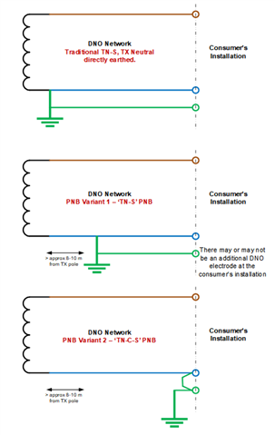
    The key differentiator, is that the transformer star point (or mid-point) is NOT earthed directly in PNB systems (whatever the variant), but is in true TN-S and TN-C-S, but the N conductor is connected elsewhere from the transformer.

    You can then argue whether the "N" conductor (I will not call it a Neutral at this juncture, because strictly, according to the International Electrotechnical Vocabulary, it's perhaps not a Neutral in single-phase or split-phase secondary transformers) in a PNB system acts as a PE conductor for the transformer itself ... but the wiring (which is what BS 7671 is concerned with) can be SNE, and therefore it's possible for PNB to be TN-S (but PME conditions would still apply).

    The following diagrams might help illustrate what I'm talking about:

  • There are further (minor) variations in the above between the DNO's (and before that the old 'Electricity Boards').

    A small number (typically 4) of consumers may be supplied by each of the PNB variants.

    In 'variant 2', sometimes each customer has their own electrode, sometimes only the first, or first and last.

  • Those are very helpful diagrams Graham, your commentary on multiple potential pole consumers each with their own earth rod explains the ENA logic of applying PME bond sizes to PNB supplies

  • Hello Graham, I have drawn my conclusions from the following reliable sources, which support my statement that PME and PNB are both variants of the TN-C-S earthing system, where the PEN conductor is split into separate neutral and earth conductors at the consumer’s premises:
    The [Electricity Safety, Quality and Continuity Regulations 2002] stipulate that a TN-C-S system is “an earthing system having a common conductor throughout the system which is used to carry both earth fault current and the neutral current of that system, and in which the voltage of that conductor is kept substantially at earth potential by connecting it to earth at one or more points”. This stipulation applies to both PME and PNB systems, as they both employ a common conductor (PEN or CNE) that carries both earth fault current and neutral current, and is connected to earth at one or more points.
    The [IET Wiring Regulations (BS 7671:2018)] specify that a TN-C-S system is “a system having one or more points of the source of energy directly earthed, the exposed-conductive-parts of the installation being connected to that point by protective conductors”. This specification also applies to both PME and PNB systems, as they both have one or more points of the source of energy directly earthed (the neutral of the source in PME and the PEN or CNE conductor in PNB), and the exposed-conductive-parts of the installation being connected to that point by protective conductors (the metallic sheath or armour of the service cable in PME and the separate protective conductor or CNE conductor in PNB).
    [The Electrician’s Guide To The Building Regulations] state that PME and PNB are both variants of TN-C-S systems, where “the distributor provides a combined neutral and protective conductor (PEN) up to a point near to the consumer’s installation. At this point, separate neutral (N) and protective (PE) conductors are provided for connection to the consumer’s installation”. This statement corresponds to both PME and PNB systems, as they both have a PEN or CNE conductor up to a point near to the consumer’s installation, where it is split into separate neutral and earth conductors. Therefore, based on these sources, I uphold that my statement is accurate and consistent with the definitions and descriptions of TN-C-S earthing systems. However, I highly respect your opinion and suspect you are right. I also invite any further evidence or arguments that contradict my claim.

  • Agreed, but regards your first point:

    Hello Graham, I have drawn my conclusions from the following reliable sources, which support my statement that PME and PNB are both variants of the TN-C-S earthing system, where the PEN conductor is split into separate neutral and earth conductors at the consumer’s premises:

    That is true of 'variant 2' in my diagrams, but NOT 'variant 1' which is split earlier than the consumer's premises.

    And the last point.

    [The Electrician’s Guide To The Building Regulations] state that PME and PNB are both variants of TN-C-S systems, where “the distributor provides a combined neutral and protective conductor (PEN) up to a point near to the consumer’s installation. At this point, separate neutral (N) and protective (PE) conductors are provided for connection to the consumer’s installation”. This statement corresponds to both PME and PNB systems, as they both have a PEN or CNE conductor up to a point near to the consumer’s installation, where it is split into separate neutral and earth conductors.

    Variant 2, the distributor provides a separate N and PE, not a PEN.

    It certainly is not that clear cut at all.

    EXCEPT that G12/5 says that PME conditions apply where PNB is used (that would be for Variant 1 and Variant 2 - although strictly only variant 2 is always TN-C-S).

    There's a little more to this, being the fact that the Neutral (as we use it in most of BS 7671) isn't always a "neutral" ... especially in single-phase systems (i.e. where the LV supply transformer is single-phase).

  • How could you! Defamatory allegations on the internet. I have purchased numerous IET publications