
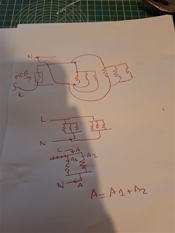
Am I correct in simplifying a ring circuit like this in theory? Assuming the loads are the same 1ohms and the distance between each load is the same as well.
Am I correct in simplifying a ring circuit like this in theory? Assuming the loads are the same 1ohms and the distance between each load is the same as well.


