Why is the PME fault detection threshold for single-phase charging piles in the UK < 207VAC or > 253VAC?
It is quite simply because the EV charging equipment standard, BS EN 61851-1:2011 stated in Clause 5 (see my highlight):
5 Rating of the supply a.c. voltage
The rated value of the a.c. supplied voltage for the charging equipment is up to 1 000 V. The equipment shall operate correctly within ±10 % of the standard nominal voltage. The rated value of the frequency is 50 Hz ± 1 % or 60 Hz ± 1 %.
NOTE Nominal voltage values can be found in IEC 60038.
I am aware that this is not the current version of the charging equipment standard standard.
There are a number of reasons a wider voltage range would be preferable, but this has to be balanced with safety.
The IET is currently working on a new standard specifically for open-PEN detection devices, that will hopefully be available in the Autumn, which proposed this range is increase (but other measures may be required for safety).
and if you're wondering if these voltage ranges correspond to PE-Earth actually being below 70V in any way ... try this discussion: Open PEN detection for 722.411.4.1 (iv)
- Andy,

and if you're wondering if these voltage ranges correspond to PE-Earth actually being below 70V in any way ... try this discussion: Open PEN detection for 722.411.4.1 (iv)
Agreed ... but to be clear, Regulation 722.411.4.1 (iv) does not mention a '70 V touch-voltage' condition, and therefore it is strictly not necessary to correlate the two, except for, perhaps:
Thank you gkenyon and Jewsbury, are all single-phase electrical systems in the UK derived from three phase electrical systems?
Normal grid voltage fluctuations may cause the voltage to exceed 253V or below 207V, when the load is too light or too heavy; I still don't understand how I can tell if the PEN is likely to break when the voltage is above 253V or below 207V. Or will the voltage be higher than 253V or lower than 207V when the PEN is open?
Thank you gkenyon and Jewsbury, are all single-phase electrical systems in the UK derived from three phase electrical systems?
No. In the public supply, the following are also used:
Note that whilst I've used 230 and 400 V being the usual stated nominal voltage, we often use higher voltage rating of transformers in the network because of voltage drop in the distribution lines, or to enable auto-voltage control via tap-changing.
Normal grid voltage fluctuations may cause the voltage to exceed 253V or below 207V, when the load is too light or too heavy;
Voltage fluctuations can (and does) cause unwanted operation of the OPDD.
In the UK, we have legislative requirements that mean the voltage at the consumer's terminals (unless otherwise agreed with the DNO) ought to maintain these limits [for the majority of the time].
I still don't understand how I can tell if the PEN is likely to break when the voltage is above 253V or below 207V. Or will the voltage be higher than 253V or lower than 207V when the PEN is open?
This link might help: Open PEN detection for 722.411.4.1 (iv)
It was also explained in the Draft for Public Comment of IET Standard IET01 for the OPDD product ... that standard is currently planned to be available in Q3 of 2024.
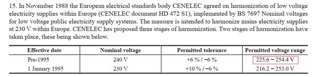
Thanks Graham, In the UK,240V is a typical power grid voltage. According to the description in Appendix 2.15 of BS7671, the upper limit of 240V voltage is 6%, that is, 254.4V. In the case that the input voltage of charging pile is 240V, can the upper limit of PME fault detection be 254.4V?
Thanks Graham, In the UK,240V is a typical power grid voltage. According to the description in Appendix 2.15 of BS7671, the upper limit of 240V voltage is 6%, that is, 254.4V. In the case that the input voltage of charging pile is 240V, can the upper limit of PME fault detection be 254.4V?
We are now after 1 January 1995, so we now use 230 V + 10 % / - 6 % at the origin. This is the supply voltage at the origin, 216.2 V to 253 V.
Regulation 722.411.4.1(iv) concerns the utilization voltage (i.e. the voltage, including volt-drop in the installation, being therefore the voltage range at the equipment) being 207-253 V.
I still don't understand how I can tell if the PEN is likely to break when the voltage is above 253V or below 207V. Or will the voltage be higher than 253V or lower than 207V when the PEN is open?
Very generally, the problem is to be able to work out what voltage the PEN conductor (and hence the exposed-conductive-parts of the vehicle) are at relative to true Earth, without having an actual true Earth reference to measure it against. The idea is to use the supply L conductor as a reference (as it's generally 230V/240V above true earth as it's earthed at the supply and and that reference isn't lost in a simple broken PEN event).
A entirely single phase supply is probably the simplest example. When the supply PEN conductor is broken, N/PE conductors on the load side of the break (including the installation MET etc) are pulled towards line voltage by any connected loads and may be dragged towards earth by any connections to true Earth (e.g. bonding to extraneous-conductive-parts). Any voltage on the installation's PEN conductor then shows up directly as a reduction in apparent voltage between PEN and L. So say the MET was at 50V and the supply 240V - L/N and L/PE voltages in the installation would be in the region of 190V. If that were the only case, the devices could be set to trip at anything below 170V and that would be that.
Many installations, including single phase ones, are fed from polyphase (usually 3-phase) LV distribution systems though. That makes things rather more complicated. The connected loads are pulling the severed end of the PEN not just towards L but in almost a tug-of-war between all three L, 120° apart. If all loads were perfectly balanced the effect of the 3 Ls would precisely balance and the severed PEN would remain at 0V (comparable with omitting the N on 3-phase circuits with no single phase loads). In practice though, loads at installation level are almost never perfectly balanced, so (thinking of a phasor diagram) the severed PEN could be pulled anywhere within a 400V triangle - so any single 1-phase load (e.g. a charge point) could see anything between 0V and 400V between L and N or PE. Hence the idea of taking what's "normal" and treating anything outside that as being indicative of a possible broken PEN.
In the UK, the supply *should* be between 216.2V and 253V (it's a statutory requirement), so normal adding or removing loads and allowance for voltage drop in the supply system should still keep things within that range. There may be some short duration excursions outside - e.g. for starting currents - but they should be limited (and the DNOs have powers to have "disturbing" equipment disconnected from the supply). Likewise routine "faults" (e.g. L-N or L-PE faults within installation) can cause the supply voltage to collapse (or increase if the fault is on a different phase) - but again the duration should be limited (faults in any modern installation are normally disconnected well within 5s). So the "normal" voltage range, plus a time delay (e.g. 5s), should avoid the vast majority of problems.
- Andy.
We're about to take you to the IET registration website. Don't worry though, you'll be sent straight back to the community after completing the registration.
Continue to the IET registration site