Checking if 1.0mm cpc on 2.5mm cable is acceptable for EICR and where the limit is

Just want to check my calculations and conclusions are correct.
(been meaning to do this for a while)

Checking if a 2.5/1.0mm cpc is acceptable on a 32A  ring final for an EICR.

In this example looking at data for MK 32 A MCB MK data sheet

In the graphs I am assuming the horizontal is PSCC/PFC. In my example I have a PFC of 700A, therefore I2T = about 5000 A/sec

Energy withstand for 1.0cpc  K2S2 = 115*115 * 1.0 = 13,225

I2t needs to be less than K2S2

5000 < 13,225  therefore I am ok.

If I look at the graph and find I2t of 13,000 it looks like I am ok for pscc/pfc  up to about 3K, bit difficult to read with linear graduation on a log scale.

In reality the B type actually switches in 10msec with 5 * rated current rather than the 100msec typically used in calculations.
  • Which tallies with the conclusion we came to when doing the calculations at college twenty years ago.

    The general consensus after doing those calculations twenty odd years ago was that a BS60898 B32 MCB could be okay, a BS3036 30-amp fuse will probably be inadequate, but the best option is probably the BS1361 30-amp fuse.”.

  • But the calculation seems to ignore the current split? 

  • hmm  in the worst case it could be  a spur couldn't it.... I suspect also in many cases of existing circuits , we probably don't really care too much if we manage to drill into a bit of old cable, and if in the process of going bang we now have to change a bit more length of it than just the little bit that got drilled or nailed.  

    The temperature assumptions that underpin the upper 'damage/no damage' limit to the PVC in the adiabatic equation only really became important once we moved away from rubber covered cables - in the older cases, where the onset of thermal degradation was much less clear, also the life of the cable even at room temp was more limited.

    Mike

  • hmm  in the worst case it could be  a spur couldn't it..

    Doh! ….it was Saturday night when I responded but I can’t even blame the beer since I have been off it for quite a while!

  • The fault could be on a spur or very close to the consumer unit so one section of cable could take the brunt of the force.

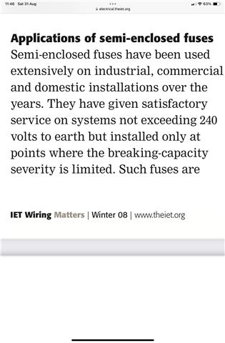
    These circuits were installed back in the 1970’s and the majority of them were protected by BS3036 re-wirable semi-enclosed fuses, the fuses and the 2.5/1.0 T&E were were only suitable if the faults were severely restricted.

    The 2.5/1.0 mm might be okay with TT earthing, but may require replacing if the earthing arrangement is changed to TN.

    electrical.theiet.org/.../semi-enclosed-fuses.pdf

  • I would assume less than 1 kA, which is realistic and if it was more than that a BS3036 fuse board needs replacing anyway.

    Weren't BS 3036 CUs conditionally "deemed to comply" to 16kA even though the individual fuses might only be good to 1 or 2kA? (in the same was as we can use 3kA or 6kA MCBs and still claim 16kA compliance).

       - Andy.

  • Its more complex - the later all enclosed fuseboards probably were qualified, at least with the more modern company cut-outs,  but there were several revisions to the design of the enclosures for hot wire fuses over the years, from prewar  'bridge wire' designs  to the later wire threaded into  a ceramic tunnel, but all wood cases to the 1950s  wooden backless ones, To many eyes all re-wirable fuses are '3036  and equivalent. but I think that not all actually were, and some enclosures were  better than others at holding the bits in under stress.

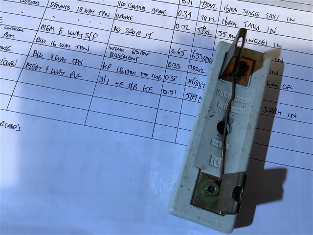
    Certainly the wylex ceramic tube ones were quite capable of firing hot gas and molten metal out of the ends while being pushed in against a bad fault - which I'm sure was a technique  forbidden in the instructions, but equally so quite common I think; and cases and covers with scorch marks and a light deposit of copper and copper oxide were not unknown - presumably in areas with a higher PSSC. I don't think any designs actually fail to disconnect at any credible domestic fault level, its more how much dust pan and brush work is needed afterwards and if you need a new carrier, or at least the block for it.

    Light emery paper or a pan scrubber will remove the metal deposits.....

    The situation was not helped by some of the older supply cut outs also being re-wireable, and in some cases things like fuseholders being rewired with random non-fusewire 'to stop it blowing'. 

    Mike.

  • The general consensus after doing those calculations twenty odd years ago was that a BS60898 B32 MCB could be okay, a BS3036 30-amp fuse will probably be inadequate, but the best option is probably the BS1361 30-amp fuse.”.

    Probably also worth considering that a couple of things have changed since those calculations were done (and anyone who did 16h Ed calculations)

    First, we now calculate at 230 V. Second, we should now apply either Cmax (1.1 factor) or Cmin (0.95 factor) to our calculations associated with thermal effects. Which you choose depends on what effect it has on the outcome. BS 7671 requires thermal effects to be considered for all prospective fault currents along the length of a circuit, from the largest at the origin, to the lowest (typically the furthest point of the circuit), which is why the 'line plot' option is always the best approach for fuses, but basically:

    • Cmin is used where we are calculating the lowest prospective fault current (typically the furthest point of the circuit) and has an effect of lowering the lowest prospective fault current by 5 % over the "old" calculations.
    • Cmax is used in calculating the prospective fault current at the origin of the circuit, and has the effect of raising the highest prospective fault current by 10 % over the "old" calculations.

    Usually (but not always) with fuses, it is the lowest prospective fault current that causes us a problem and Cmin would be applied for that.

    With circuit-breakers it's slightly more tricky, but if a circuit-breaker is providing ADS, then typically the breaking time is 0.1 s or less, so we are considering using let-through energy calculation as required by BS 7671, and this typically (but not necessarily always) means that Cmax would provide the worst-case.

  • The physics cannot have changed, but are you saying that the understanding of it has improved? Or have the circuit protective devices changed?

    I recall one of my tutors saying that cleverer people had decided that a reduced CPC was safe, so just accept it.

  • its more how much dust pan and brush work is needed afterwards and if you need a new carrier, or at least the block for it.

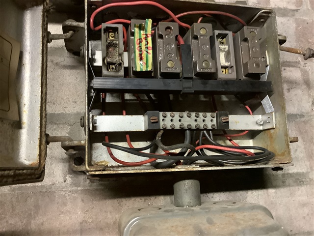
    Like this one, cover lying open, in a store bunged with combustible items;

    Of course, you can always make up your own standard fuse arrangement;