Adequate protection of balanced 3P Circuit , no neutral , no cpc

Hello - we have an installation that is proposing to use multiple sets of LV AC in parallel, terminated at at ACB at load side and taken directly from a transformer at supply side. What is the best way of protecting the cable where the TX does not include a neutral / earth point so there is no cpc. 

Plan is to install using unarmored single core cables run in trefoil.

How could we adequately monitor / protect these cables? 

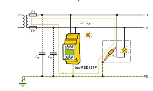
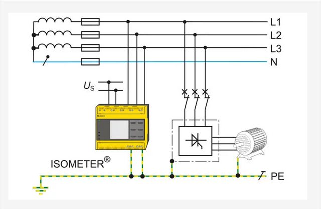
Would an IMD device be ineffective as there is no earth fault return path for the AC circuit that is running in i.e. no cpc dedicated or armoured or is it still possible to place an IMD monitoring each phase and provide a dedicated earthing connection for the IMD only? 

What other options for protection are available in this scenario? 

  • what happens in fault ? - if we ground one of the 'phase' cables does the system keep running, with the other 2 phases now at  higher offset voltage to earth and the faulty one at zero volts? Is this acceptable to the load side wiring ? On second fault on another phase over current will operate...(!)

    If the 3 phases are fully floating what stops them floating up to a voltage that is a sizeable fraction of the transformer primary voltage, via the inter-winding capacitance ?

    I assume from your description the TX secondary is a delta ? One can externally create a centre for fault detection / earth leakage tripping with 3 identical impedances - special ZZZ transformers are made for this.

    A bit more info would help.
    Mike

  • What sort of protection do you have in mind? Overload, faults between live conductors, faults to Earth?

    One traditional solution for LV where there's no c.p,c. is to use double/reinforced insulation - i.e. Earth faults are made sufficiently unlikely that ADS isn't needed - but that might be tricky if you've got metalclad switchgear. Disconnection for other faults generally requires an overcurrent protective devices.

    Is the intention to create an IT system?

       - Andy..

  • Dyn11 TX, so the secondary does has a star point but the OEM has specified only brining phase conductors to the LV Circuit Protection Device for their equipment. 

  • was thinking that providing an IMD monitoring all phases and a suitable earth reference point would be sufficient?

    we do need to have as much play on the cables as possible because we have a limited bending radius, so was thinking coil-lead-end or H07RN-F flex cables we would use, sufficiently sized for the install conditions 

    Yes, it is the intention to create an IT system between the wye side of the transformer and the LV device we are connecting to. 

  • Why are you establishing an IT earthing system? What does the design call for? Is it a new installation?

  • Realise that anything more than the smallest IT system (perhaps one UK shaver in a UK shaver socket !) is not really full free of the influence of earth, as the capacitance between the wiring and the environment conspires to provide a degree of AC coupling. The 'n' point of the transformer secondary may need to be brought out, if only to be connected to local earth via the fault / insulation monitoring via  a high impedance. In that sense at least, you do have a CPC of sorts, and any cable tray or basket should still be connected  in the normal way to the building MET and so on, but not to the TX neutral. This example is IT single phase but shows the idea - note how the wiring capacitance  'Ce' complete the fault path- in a large installation this impedance becomes significant, and limits the size of an IT system for a given maximum leakage current.


    or more like your description, where N is not needed.


    The earth leakage detection will need the capacitance (and insulation resistance) from the 3 phases to be fairly stable and well balanced, but this happens automatically when cable lengths and mounting  methods are the same . There are earth currents, but they are very limited.

    https://www.bender-uk.com/fileadmin/content/BenderGroup/Documents/Article/en/RCDs_in_Steckosenstromkreisen_von_IT-Systemen_EN.pdf

    is worth a read if you are unsure about this.
    As to be fair is quite a lot of the Bender literature, but note that some is in German, and some that is in English, should be read, understanding it was written in German and then translated !!

    https://www.bender-uk.com/know-how/literature/

    Mike.

  • Dyn11 TX

    In addition to Mike's points above, there's also a potential issue with capacitive coupling between the HV and LV windings of a transformer - if the secondary isn't earthed the whole secondary side can be dragged up to some significant proportion of the HV potential - not much current behind that of course, but it can put a lot of stress on the secondary insulation (as it's several kV from Earth, referenced to Earth via the HV system). As I understand it transformers intended for IT systems will often incorporate an earthed screen between the windings or something similar to mitigate those risks, but it's something to be aware of if you're trying to create your own IT system off the back of an ordinary transformer intended to normally supply TN systems.

        - Andy.

  • Realise that anything more than the smallest IT system (perhaps one UK shaver in a UK shaver socket !)

    The secondary of a shaver socket is not an IT system, but Electrical Separation (Section 413). Provision of electrical separation to more than one item of equipment can only be done if the installation is under supervision of skilled or instructed persons (Section 418).

    An IT system, however, is a form of ADS (Section 411, Regulation Group 411.6), and has a protective conductor from a means of earthing which is either

    • not connected to the neutral point, or midpoint, or a live conductor of the system
    • is connected via a resistance to the neutral point, or midpoint, or a live conductor of the system
  • Apologies, that shaver example was sloppy, as not exactly IT, but it does illustrate the point that not all systems are TN. The general idea of an off-earth loop is the same, and some of the problems. But given the absence of fault detection for shavers, there is a good reason you can't get splitter adaptors for UK shaver plugs (except off the internet, but like 20A rated 13A fuses, they should not exist) - the safety idea is then only one load at a time. (though europlug splitters do fit and rather undo the safety case for europlug shavers.)
    Mike.

  • thanks, yes this makes sense as there will always be the inherent capacitance on the LV side in the IT system. Think 442.2 & Table 44.1 make sense in this context as well as 44.2. 

    One additional query that is coming to mind is that at the AC ACB we would have SPD's . aside from rating these at a L-L voltage to cover continuous operation under a first fault. are there any key considerations for SPD's in this position ?

    in terms of wiring diagram / how this will look i am thinking Fig16A4 for position of the SPD.  


1 2