Voltage Monitoring Relays - what delay?

There's been some talk recently of using voltage monitoring relays (e.g. https://uk.rs-online.com/web/p/monitoring-relays/1026131 or https://uk.rs-online.com/web/p/monitoring-relays/0122215), and a suitable contactor, to protect an installation against long duration overvoltages (so not brief surges, more like a single phase installation being fed something approaching 400V due to a broken N in the 3-phase distribution system).

I can see pros and cons to such an approach, but let's go with it for now for the sake of debate...

What I've noticed that all these devices seem to come with a programmable delay (sometimes overridden for large voltage errors, sometimes apparently not) which implies that the installation may have to withstand an overvoltage for some period of time - so the question is how long would we expect things to survive? I can see simple resistive heaters hanging on for a a fair fraction of a minute before overheating becomes catastrophic, filament lamps I suspect won't last anything like as long. What about electronics? or small single phase motors?

I suspect we're treading a fine line here, too short a delay and it'll be tripping out on the slightest glitch (next door's storage heaters switching on, or I suppose these days heat pumps, or a brief fault in some other installation connected to the same distribution system) which wouldn't be ideal even if the installation is only disconnected for a few seconds before being automatically restored. Too long and I presume the risk of damage increases. Where's the happy medium (is there one?)

  - Andy.
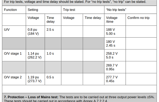
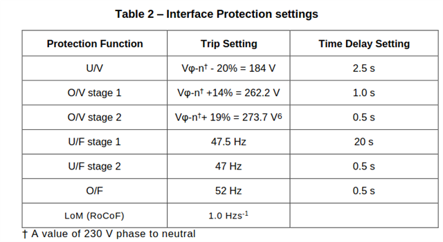
  • The OV/UV thresholds and time delays presented in G98 and G99 would be a good start.

    If the installation has generation (including PV) that can operate in parallel with the grid, then to 'trip' the installation "inside" these limits is likely to contravene ESQCR and any connection agreement.

  • For those not so familiar. the standards are freely available here G99

    And here G98

    The limits in question for connections at 230V are the same in both standards, but presented slightly differently.


    and

    Personally, I'd like to see a much faster trip time for over-voltages  like 400V appearing where 230 ought to be, as at that point things like the capacitors in most designs of SMPSU will be letting it all hang out within one cycle period of the mains,   but that's my electronics background at work.
    Even at 270V smaller conventional transformers and ballast chokes wound for 230 are likely to be saturating at peak flux, B being proportional to dV/dt and all that, so some very unpleasant currents are likely to be flowing and some very unhappy buzzing noises ensuing - but the damage there involves heating thermal masses of grams to kilos of metal so to survive a few seconds is realistic. Note that for inductors  the most destructive combination is low frequency and high voltage - which does not usually occur together in a conventional rotary generating system.

    Note that surge arrestors typically clamp voltages to well over this sort of level, between 600 and a thousand volts or so but that is much shorter duration, and  the worst has all happened and subsided in a few tens of microseconds, and on that timescale the natural inductance and capacitance of mains wiring tends to limit the energy reaching the most delicate victims (normally the semiconductors, with sub-millisecond fail times for over-voltage).

    Mike

  • Thanks guys - some definite food for thought there!
       cheers

          - Andy.

  • I suppose it wouldn't be against the letter of G98/99 to disconnect ordinary loads in a shorter times, especially for larger over-voltages (if leaving any embedded generation connected to the grid) - so I could still use a faster disconnection time to provide some protection to more sensitive loads,

    Maybe not in the spirit of keeping the grid stable, but larger over-voltages I suspect are more likely due to a local LV faults rather than a wider grid situation - something approaching 400V L-N as a result of a broken PEN in LV distribution system seems much more likely than 400V appearing due to the HV network running at 170% normal voltage (where there are no distributed Ns to break or star connected loads, that might have produced similar a condition to a LV broken N). And disconnection due to a local LV fault is hardly going to affect wider grid stability.

       - Andy.

  • As a matter of interest are these sort if over voltages really a big issue especially as now virtually every time the DNO dig up a duff joint for repair they earth the neutral with a copper rod or length of wire I've seen it done round here on repairs once when they put in a new linky box  and once when they put in some new joints  only the one with  feed to customer was earthed the other thru joints didn't seem to be

  • Well, one of the reasons they add NE links and extra electrodes when they dig up blown joints is exactly because of this sort of problem. Not sure what cable you have round your way but here we have a lot of copper singles overhead providing TT that is very reliable but pre-war, so a bit undersized for modern demand,  and on the postwar housing estates some terrible underground 1960s and 1970s Aluminium clad stuff that presents as either TNS or  TNCS at the customer service head,

    Where the plastic jacket has been scraped either at installation or by tree roots or settlement over time, the aluminium gets damp, and then over some years converts to the oxide as an insulating white encrustation, and at that point, depending which bit of the network you are on,  just the earth or the PEN is lost. We seem to have a few of those events a year but not all lead to full 400V on the live, it depends on the loading at the time it finally goes open circuit.  

    The DNO seem to be well aware of the issues as repair teams  turn up very fast to those ones.

    Mike.

  • I suppose it wouldn't be against the letter of G98/99 to disconnect ordinary loads in a shorter times,

    No, but it will affect grid stability if this approach is adopted en-masse.

    EMC testing does include testing to cover voltage spikes, transitions, interruptions and flicker, to cover "short time" events, so I would be concerned whether products that need such disconnection actually conform to the essential requirements of legislation.

    Worth also looking at BS EN 50160 which looks at the quality of public electricity supplies.


  • The EMC limits are a lot closer to the surge arrester case - certainly no big upset condition that is sustained for a time scale of whole seconds.

    In terms of spikes,  not all kit with a CE mark needs to be tested anyway, but even if it was the longest single surge test in  IEC 61000-4-5 is the 700 microsecond one, and often mains inputs are only tested to the class 1 easy one of 500V for 50 microseconds.. Hold that voltage for ten times this duration and a lot of electronics will be dead.

    The EFT (fast transients) test calls up bursts of 75 pulses of 50 nanosecond duration, spaced 100usec apart  with burst repeating 3 times a second, may also be tested at 500V or higher, but that is also a lot less energy than a sustained overvoltage long duration event.

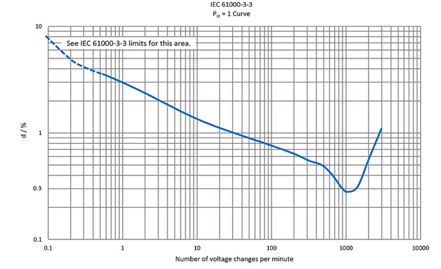
    Flicker 61000-3-3 is generally stepped voltage changes of less than 10%, and the test levels of the fluctuations are a lot less if if repeated  more than a few times per minute.


    Y axis, "d" is the voltage droop or uptick, 10%, 1% or whatever, and the frequency in events per minute is the X axis.


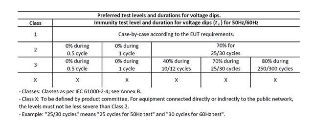
    Dips however are allowed to be quite severe, to 70% of mains voltage for up to 25 cycles at a time on a 50Hz system, 


    In summary, nothing in an EMC test that includes all the possibly applicable IEC 61000 tests, verifies or assures any protection against significantly out of spec over-voltages (say 300v plus) on the mains that persist for more than,  at best, just under a millisecond, and for most domestic gear, probably more like 50 microseconds..
    I'd not want to rely on the CE / UKCA mark alone to protect me ;-)
    Mike.`


  • now virtually every time the DNO dig up a duff joint for repair they earth the neutral with a copper rod or length of wire

    Individual additional electrodes make only a small difference as the resistance of the soil around the rod/wire is often into the tens if not hundreds of Ohms while the remaining connections and/or loads, which are pulling the other way as it were, are often in the Ohms or small fraction of an Ohm.

    If you're lucky and have many electrodes on your side of the break, your earthing system may well be kept closer to true Earth, but often at the expense of the transformer's star point drifting further way - which skews the L voltages (compared with Earth) and your L-N voltages are still liable to be outside of the normal range. There's no easy fix for these sorts of things.

       - Andy.