Guidance Note 3 Inspection and Testing 2022 Appendix C

Guidance Note 3 Inspection and Testing 2022 Appendix C


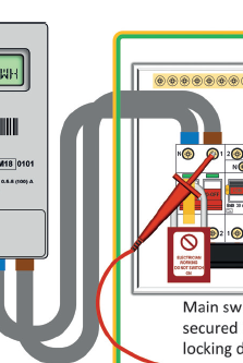
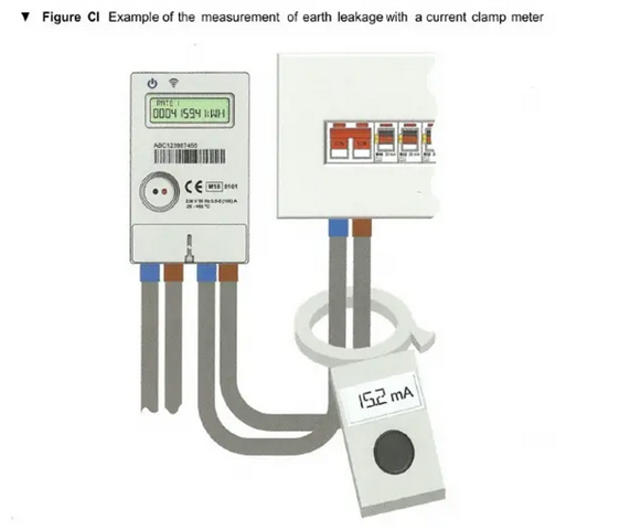
Is the diagram / picture incorrect?  Should it not show the Neutral/Blue in the middle under the meter and the Line/Phase on the outer part?  See attachment


As always please be polite and respectful in this purely academic debate.


Come on everybody let’s help inspire the future

  • While the polarities are correct at the meters, (although the colours/ tapes are reversed at the terminals), BOTH consumer units are indeed reverse polarity.

    I'm not seeing that. Line conductor on right hand side of isolator (terminal 1), feeding through to busbar below on RHS (terminal 2)... neutral link from bottom-left to neutral busbar not shown.


    In fact, whilst now not always followed, traditionally, terminals in single-phase systems were frequently arranged to go "clockwise" from the top, similar to the concept of line at the bottom-left if PE at top-centre in socket-outlets.

    Of course, when providing illustrations for industry guidance, making things look too much like a particular product from a real manufacturer is to be avoided.

    I do, however, take the point that it wouldn't be easy to route the tails inside the CU in the Figure in Appendix C.

  • I do, however, take the point that it wouldn't be easy to route the tails inside the CU in the Figure in Appendix C.

    Fine stranded tails! (As discussed previously.)

  • Firstly, apologies to Sergio, I shouldn’t have hijacked his post! However, to answer AJ’s question, yes, the neutral is through the clamp. 

  • Fine stranded tails! (As discussed previously.)

    Grin

  • Actually, it looks like I have made a silly mistake, the neutral is going through the clamp but not in the right direction! Thanks AJ!

  • Hi Lyle

    You are more than welcome to hijack any of my posts.  After all we are all here as a group of engineers discussing engineering and trying to impart our knowledge and curiosity.

    Come on everybody let’s help inspire the future

  • With reference to the picture I would also like to see it show the tails clamped/Cleat/supported between the meter and the CU. 

    Inside the CU itself I would like to see the tails be either clamped or double screw terminal on the main switch.  A combination of both would be inherently the best solution.  Sample pictures below (other brands are available)

  • It would look good if I was added to  Acknowledge contributors on my IET Career Manager section as

    Professional Services, Papers & Presentations