Cable size between equipotential earth bonding bar and distribution board in a Group 1 medical location

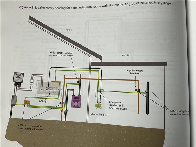
The IET regulations require that the resistance of the conductors, including the resistance of the connections, between the terminals for the protective conductor of socket-outlets and of fixed equipment or any extraneous-conductive-parts and the equipotential bonding busbar (EBB) shall not exceed 0.2 Ω.

However the cable connection between the EBB and the Main Distribution board, is not defined, (identified in red in the image below) - either in terms of:

 1 - maximum resistance 

2 - minimum cable size 

3 - if the cable needs to connect to the distribution board that serves the room or should go back  to the Main distribution board.

4 - if there are number of EBB's can they be connected by a single cable in a daisy chain arrangement back to the distribution board.

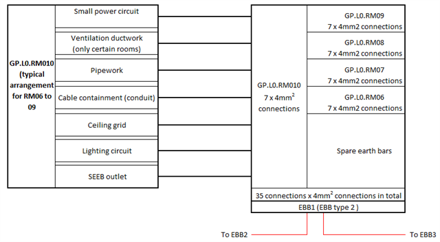
Is any able to provide guidance on the four questions above?

  • BS7671 does not actually mention “Touch voltage” it refers to simultaneously accessible parts.

  • I cannot see a definition of touch voltage in BS7671, but here is the National Grid definition:

    commercial.nationalgrid.co.uk/.../229258

  • The requirement is for Supplementary protective equipotential bonding:

    A quote from The IET Wiring Matters issue 76 July 2019.

    What is supplementary protective bonding?

    A supplementary protective bonding conductor is used to connect simultaneously accessible exposed conductive parts and accessible extraneous-conductive-parts to prevent a hazardous potential difference from occurring between them. It is usually only required in special locations, such as rooms containing a bath or shower or when automatic disconnection of the supply cannot be achieved.

    https://electrical.theiet.org/media/2139/issue-76-july-2019.pdf

    So, are the touch voltages and circuit protective devices disconnection times completely irrelevant, because both the parts you may be simultaneously touching could have 240 volts on them indefinitely and that is the issue the Additional Protection provided by the supplementary protective equipotential bonding is intended to resolve?

  • Once you get past 5 s, the zones on the graph do not change.

    Agreed, but the touch-voltage-for-time and touch-current-for-time (with the available voltages and currents) might well show an exposure time of less than 5 s is needed.

  • So, are the touch voltages and circuit protective devices disconnection times completely irrelevant, because both the parts you may be simultaneously touching could have 240 volts on them indefinitely and that is the issue the Additional Protection provided by the supplementary protective equipotential bonding is intended to resolve?

    It would only work that way, if you based the resistance between simultaneously-accessible conductive parts on achieving the relevant voltage for the prospective fault current ... but the formulas in 415.2 bases it on Ia, not Ipf.

    There is a good reason to do so

    BS7671 does not actually mention “Touch voltage” it refers to simultaneously accessible parts.

    Agreed ... but we do see the term in the latest IEC 60364-7-710, and also we saw it in the Draft for Public Comment for what is now planned to be Amendment 4:2026.

    Whilst what we are talking about is a hand-to-hand touch-voltage, I agree that BS 7671 and IEC 60364-7-710 appears to be happy with a calculation based on Ia and a voltage of 25 V AC / 60 V DC, with a stipulated maximum resistance of 0.2 Ω, whereas product standards would measure touch-voltage and touch-current with a test circuit that mirrors a theoretical impedance of the human body.

    There's certainly a very good reason NOT to do that in Sections 701, 702 and 710 ... because the body impedance under some conditions in those locations is, to the best of my knowledge, not accurately known, or at least documented, at this time.

  • I have a particular scenario in mind in which there is a complete failure of the Protective Measure- Automatic Disconnection of Supply (ADS) due to circuit protective devices both MCBs and RCDs, as well as fuses and RCBOs, being completely ineffective, because of a failure of the earthing system, which results in there being a recommendation to install supplementary bonding to provide additional protection.

    Edit- I have just checked and as I thought, Graham is the lead author of the book I am looking at and I’m sure he knows where this is going.

  • because of a failure of the earthing system,

    Such an arrangement would not meet the requirements of Section 411, and, if a workplace, possibly not the Electricity at Work Regulations (Regulation 8) either?

    It would be better to use an alternative means of protection against electric shock, such as Class II equipment or SELV.

    To be clear, a broken PEN conductor is not necessarily a broken earthing system ... although it does involve EPR due to a broken neutral. However, I can see cases where it can be ineffective earthing in which case see Regulation 114.1 of BS 7671 and the ESQCR.

  • BS7671 114.1 states that for a supply given in accordance with ESQCR it shall be deemed that the connection with Earth of the neutral of the supply is permanent.

    BS7671 Section 722 and Annex A722 does seem to contradict that statement, and the EVSE COP guides us to taking an Open-PEN fault into consideration with supplementary bonding being additional protection that we may consider installing in some circumstances.