Group 1 Medical location - maximum resistance between EBB, socket outlet and exposed conductive part - part 2 of 2

Follows on from part 1 of 2, previous post.....

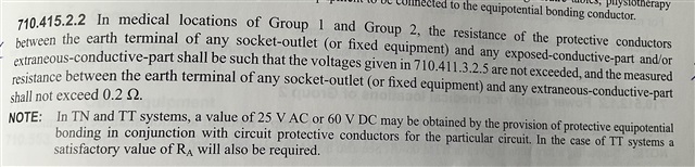
Clause 9.12.1 of Guidance note 7 states:

However it also states:

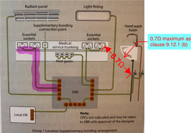
From the below diagram. I have added in red text, where I have interpreted a typical example of where the 0.7 ohm maximum resistance has to be applied. As part (c) of the clause states in general a  in general a value of 0.35 ohm can
be expected between the EBB and the earth terminal of any socket-outlet (or fixed equipment) and any exposed-conductive-part and/or extraneous-conductive-part.

For sizing of the conductors between the equipotential bonding bar (EBB) and the of bonded items, (example highlighted in pink in image below) - what should the maximum resistance be?

  • As I understand it, the resistance between the tap, which is the extraneous-conductive-part that people will touch and hold, and the socket earth terminal needs to be less than 0.2 ohms.

  • Agreed.

    However, the tap might not be an extraneous CP. It depends upon how the water gets there.

  • Some of the explanatory wording seems more mystifying than perhaps it could be, but the underlying principle seems clear enough - given a requirement for a certain maximum reading between any two points (that loop consisting of two bonding conductors) - one easy way of ensuring that would be to limit each of the conductors to no more than half the allowance - so 0.35Ω for 0.7Ω or 0.1Ω for 0.2Ω. I guess at a push you could allow any one conductor to be higher, but all the others would have to be correspondingly lower to compensate and it all gets a bit messier to calculate (and much more difficult for any future additions or alterations).

       - Andy.

  • I guess at a push you could allow any one conductor to be higher, but all the others would have to be correspondingly lower to compensate and it all gets a bit messier to calculate (and much more difficult for any future additions or alterations).

    It seems remarkably simplistic to divide the limit value (be it 0.2 Ω or otherwise) by 2.

    The EBB is required to be "in or near" each location (710.415.2.3) and "near" generally means, "immediately outside the room", so the EBB may well be adjacent to at least some sockets. It could even be on the other side of the wall.

    The length of 4 mm² cable with a resistance of 0.1 Ω is 22 m (and 13.5 m for 2.5 mm²; 8 m for 1.5 mm²) so it is not a particularly challenging target.

  • The max resistance needs to be whatever it needs to be to keep the touch voltage to 25V. generally 0.2 but that is based on 20A type B Circuit breaker(for group 2 locations) Group 1 we have RCD protection on all circuits so mostly compliant by default..

  • The design value is 0.1 ohms.

  • There is an excellent article available on the internet written by Ian Chell MSc FSRP a Birmingham City University visiting lecturer, who is working with Viji on the Medical Device module at the university.

    medical-locations.co.uk

    This article was published on the 30th September 2019, after the requirements for Medical Locations were revised and updated in the current edition of BS7671 The Wiring Regulations.

    medical-locations.co.uk/.../Pocket-Guide-for-Medical-Electrical-Installations-30-Sept-2019.pdf

  • to keep the touch voltage to 25V.

    Is that to be read more as "substitute 50V with 25V in the formula of 415.2.2" rather than "keep the touch voltage to 25V under all circumstances" - given that fault currents exceeding that necessary to open the protective device within 5s will usually result in higher touch voltages (if for reducing lengths of time).

       - Andy.

  • That is an interesting document, but I am a little surprised to see  the insistence of all sockets being on the same phase.
    I'm also surprised by the recommendation to use 4mm to 'banana plug' adaptors and  wander lead to verify this - testing an in service installation this means the wander lead is connected to the reference phase. Now  the short lead in the testers hand is current limited via the meter - which is probably a high impedance unit, reducing any potential for shock with contact with the exposed banana.  I appreciate the test leads are shrouded bananas, but in a working ward or similar I'd have thought a long live single inuslated  wander lead is some way from ideal.
    Any what is the risk to patient of having 2 phases present anyway ? One phase to earth is the far more common failure mode.

    Mike.

  • An interesting read. I spotted the "Medical IT socket-outlets" (not something I was aware of) and did a search to better understand what there were.

    One point that came out was the recommendation(?) that they should be unswitched and then a discussion about medical-it-socket-outlets and who's choice it was, plus that the switched sockets er easily available on line e.g. selectric-smooth-13-amp-blue-medical-socket-outlets (google's 1st listed)

    Definitely some interesting considerations.