Simultaenous Contact

Good afternoon all, 

I am seeking the collective views of the group regarding the issues we are currently encountering within the EV installation environment in relation to simultaneous contact.

In simple terms, we are seeing a significant number of installations where customers have lamp posts located within their driveways. In many of these cases, it is not possible to achieve the recommended 2.5‑metre separation distance.

My position is that, where physical separation cannot be achieved, the application of layered protection at the EV charge point and associated switchgear would leave the customer in no worse position than prior to the installation. It is accepted that the proposal only outlines protection on the vehicle, but there are no other solutions for industry, are we with the protection detailed taking enough measures to carry out an install and in affect leave the install without a subsantial increase in risk?

My proposed approach to managing simultaneous contact risk would follow a structured hierarchy as set out below:

  • Can the maximum separation distance be achieved?
  • Can barriers or enclosures be installed to prevent simultaneous contact?
  • If neither of the above options are achievable, can layered protection provide an acceptable level of risk mitigation?

With layered protection, the proposed measures would include:

  • Installation of a compliant open‑PEN (O‑PEN) protective device
  • Provision of a double‑pole 30 mA Type A RCBO
  • Use of a charge point - M3 21 mA protection

Based on the above, the assumption is that, if all protective measures are correctly installed and verified, the installation would incorporate:

  • Automatic disconnection within the required times
  • Residual current protection
  • Open‑PEN fault detection

This combination of protections would significantly reduce the likelihood of a fault condition persisting for any meaningful duration.

On this basis, the key question for consideration is:

Where physical separation and barriers are not achievable, would it be considered acceptable to proceed with installation relying on this layered protection approach?

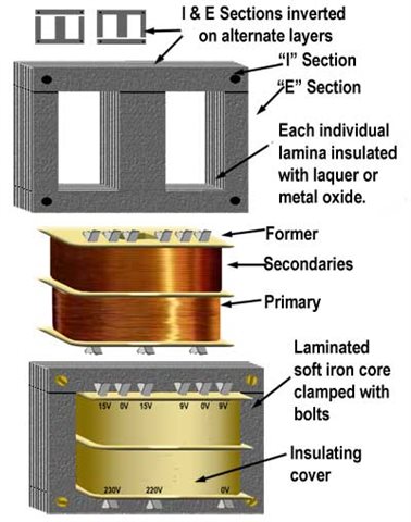
  • Probably not much change from a cube of side 40cm and a weight of ~ 75kg by the time you add the windings and the enclosure.

    Not a bad guess! - e.g. https://www.farnell.com/datasheets/3744957.pdf

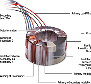
    Toroidal ones seen to come in at about half the weight though - e.g. https://www.victronenergy.com/upload/documents/Isolation_Transformer_8000W/108939-Isolation_transformers-pdf-en.pdf 

    It's not clear whether either actually meet BS EN 61558-2-4 though and even those make the charge point itself look sensibly priced.

       - Andy.

  • For full fault protection you probably want both the two pole RCD drawn and a three pole RCD encompassing L, N and PC between the two pole RCD and the transformer / N--PC link.

    It is unclear why the PC exists as it looks like an opportunity for fortuitious earthing which is the opposite of what we want here.

    No, definitely not a 3-pole device. 

    The PC is required to do two things:

    (a) As others have said, permit EVSE (charging points) and EVs that incorporate protective conductor monitoring to actually permit charging; and

    (b) As the EV is Class I equipment, and EVSE may be, or incorporate, Class I equipment, it is absolutely needed to permit the RCD to operate for a fault between a live conductor and an exposed-cponductive-part given (a).

    This type of system, with protective conductors connected to a live conductor, and possible Earth (but not necessarily) is used quite frequently with temporary generating sets, and is described in BS 7430:2026 as 'IN-S'.

    The RCD located immediately after the source, with the live conductor to PC referencing point on the source-side of the RCD, is absolutely vital for safety, to prevent a very nasty surprise, if the live conductor not referenced to the PC becomes accidentally Earthed (say if a cable is partially damaged).

  • No, definitely not a 3-pole device.

    The PC is required for two reasons.

    First, as others have said, it allows EVSEs and EVs with protective conductor monitoring to recognise a valid protective conductor and permit charging.

    Second, because the EV is Class I equipment, and the EVSE may also be, or incorporate, Class I equipment, the PC is needed to allow the RCD to operate for a fault between a live conductor and an exposed-conductive-part.

    This sort of arrangement, with protective conductors connected to a live conductor and possibly to Earth, but not necessarily so, is used quite often with temporary generating sets. It is described in BS 7430:2026 as “IN-S”.

    The RCD immediately after the source is absolutely vital, with the live-conductor-to-PC referencing point on the source side of that RCD. Otherwise there is a real risk of a nasty surprise if the live conductor that is not referenced to PC becomes accidentally earthed, for example through a partially damaged cable.

  • I think Mike’s point is important: a shared buried metallic service is not automatically equivalent to “better earthing” in the sense people sometimes imagine.

    It may reduce impedance between the connected points, and it may provide some contact with the surrounding soil, but those are two different effects. If the metallic pipe has a much lower longitudinal resistance than the soil path, most of the current-sharing is still dominated by the pipe-to-pipe metallic connection, not by any magical improvement in connection to remote earth.

    So bonding common metallic pipework can improve equipotential bonding and reduce voltage differences between exposed/extraneous parts, which is valuable. But it should not be assumed to create a reliable earth electrode unless its length, condition, coating, joints, burial environment, and contact with soil are known and suitable.

    The gas-pipe example shows the trap well. A buried pipe may look like a long electrode, but electrically it may behave more like a very good conductor linking two points, with only a comparatively weak leakage path into terra firma along the way. In some cases it helps; in others, especially with coated, jointed, replaced, plastic-interrupted, or poorly soil-contacted services, it may contribute very little as an electrode.

    So I would separate the issues:

    1. bonding metallic services for touch-voltage control and equipotential purposes; and
    2. relying on those services as part of the earthing electrode system.

    The first is often sensible and required. The second needs evidence, measurement, and caution.

  • That’s actually a clever low-cost approach. Using standard uPVC half-round guttering as a protective shell around lamp columns has a lot going for it: it’s readily available, lightweight, weather-resistant, non-conductive, and familiar to maintenance teams.

    For 100 mm columns, two 112 mm half-round sections secured with stainless steel jubilee clips could form a reasonably snug enclosure. Larger columns could use 150 mm sections, while three sections arranged in a trefoil configuration could accommodate intermediate or non-standard diameters.

    A few refinements could make the concept more practical for DNOs and local authorities:

    • Incorporate clear polycarbonate inspection windows (more impact-resistant than acrylic/Perspex) to allow asset IDs, inspection labels, and condition markers to remain visible without removal.
    • Alternatively, duplicate asset labels on the outside of the enclosure using UV-stable printed markers or QR codes.
    • Use tamper-resistant worm-drive clips or simple lockable band clamps to discourage vandalism while still allowing rapid access for maintenance crews.
    • Add drainage slots and ventilation gaps at the bottom to prevent moisture accumulation and corrosion.
    • Consider UV-stabilised black uPVC to maximise service life and maintain a discreet appearance in street environments.

    The biggest advantage is that it avoids bespoke fabrication. Installation would require little more than off-the-shelf components and a screwdriver, making it quick to deploy and inexpensive to replace if damaged. For trial schemes or temporary mitigation of column corrosion and impact damage, it could be a surprisingly practical “cheap and cheerful” solution.

  • Thanks Mike, that is a very useful explanation.

    I agree that using an isolating transformer may remove the PEN-loss issue, but it does not automatically make the arrangement risk-free. The floating secondary is an important point, especially if the vehicle body and the secondary side can rise to an undefined potential relative to true earth.

    The comparison with portable generators is helpful. Unless the secondary arrangement is properly referenced, monitored, and protected, a fault from the secondary side to earth could create a hazardous touch-voltage situation around the vehicle.

    The size and practicality are also significant. A 7 kW transformer is not a small domestic accessory; once weight, enclosure, losses, ventilation, fault protection, and installation requirements are considered, it may become less attractive than using a compliant EV charging arrangement designed for open-PEN protection.

    So I would say the transformer idea may be technically possible, but only if designed as a complete protective system, not simply as a way to avoid PEN-loss concerns. It would still need proper earthing strategy, fault protection, and compliance with the relevant wiring regulations.

  • It would still need proper earthing strategy

    Or rather unearthed strategy - the whole point being to avoid the problems from (differing) earth references. Separated systems (and variants such as IN-S) are well known and long recognised by wiring regs - as well as portable generators you can look at shaver sockets (and other situations where one item of current using equipment is used) section 413 of BS 7671, similar to multiple items (418.3), unearthed supplies (including by transformer fed from the grid supply & a  N-PC link feature) in mobile and transportable situations (section 717) and of course the specific situation here - in section 722.

    Nothing involving LV electricity is ever entirely risk-free (especially in 2nd fault or double fault from single event situations)- the damaged flex on conductive soil is a classic risk even in conventional ADS systems - the usual mitigation being the addition of a 30mA RCD. Sections 722 and 717 take exactly the same approach where the separated installation extends outdoors.

       - Andy.

  • Thanks Andy, that is a useful clarification.

    I take your point that in this case the objective is not to establish another earth reference, but rather to maintain separation and avoid the risks associated with differing earth potentials and an open PEN condition. The examples you have given from BS 7671, including Sections 413, 418, 717 and 722, show that separated and unearthed systems are already recognised approaches where the conditions are appropriate.

    My concern was less about the principle of electrical separation itself and more about ensuring that the complete installation remains safe under foreseeable fault conditions. As you say, no LV system is entirely free from risk, and the regulations generally rely on a combination of separation, fault protection, RCD protection and other measures to reduce risk to an acceptable level.

    I agree that if a separated supply arrangement is designed in accordance with the relevant requirements of BS 7671, then the discussion becomes one of demonstrating compliance and managing residual risks, rather than simply whether the transformer removes the PEN-loss issue in isolation.

    Thanks for the references they are helpful in putting the proposal into the wider context of established wiring system design.

    – 

  • Toroidal ones seen to come in at about half the weight

    Well toroids have windings around almost 100 % of the magnetic material , but conventional cores with a  centre leg and 2 sides only wind on the centre, the outer leg close the magnetic path but are outside the windings.


    so the wound section is representing sightly less than half the iron, hence the doubling of weight  - and also the halving of inrush. Toroids are smaller but  are really bad at burning switch contacts unless there is a soft start circuit and also something of a cow to wind. The machines are fun to watch ;-) Transformer solutions at the multi kW  power level are not in the domestically normal category the main customers are DNOs, and they want something bigger, and that lack of a market  is reflected in the price.

    Mike. 

  • The floating secondary is an important point, especially if the vehicle body and the secondary side can rise to an undefined potential relative to true earth.

    Isn't that the same with electrical separation, which has always been permitted for Class I equipment.

    a fault from the secondary side to earth could create a hazardous touch-voltage situation around the vehicle.

    That's what the RCD at the output of the transformer (after the L2-PC separation) is for ... to protect against a second fault. This conforms to BS 7430:2016 as well as following guidance in A722 of BS 7671.

    The size and practicality are also significant. A 7 kW transformer is not a small domestic accessory; once weight, enclosure, losses, ventilation, fault protection, and installation requirements are considered, it may become less attractive than using a compliant EV charging arrangement designed for open-PEN protection.

    Yes, size, weight, cost and inrush currents are the key issues with this approach. However, I understand they are commercially available for those cases which can't be made to be conformant in other ways at the moment.