
Hello everyone,
I have prepared this learning summary on Cable Installation Reference Methods A–F, based on BS 7671:2018+A4:2026, Appendix 4, Table 4A2.
The purpose is to explain how the cable installation method affects heat dissipation, current-carrying capacity and cable size selection.
Why do reference methods matter?
The way a cable is installed affects how easily heat can escape.
A cable installed in free air can normally carry more current than a cable enclosed in conduit, trunking or surrounded by thermal insulation.
Therefore:
Correct reference method = correct cable current-carrying capacity and cable size selection.
Cable selection rule
The basic design relationship is:
Ib ≤ In ≤ Iz
Where:
- Ib = Design current of the circuit
- In = Rating of the protective device
- Iz = Current-carrying capacity of the cable after the relevant correction factors have been applied
The installation reference method is used to identify the appropriate cable-rating table and the correct value of Iz.
Reference Method A
Method A generally applies where cables are installed in enclosed routes or locations where heat dissipation is restricted, such as: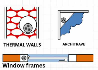
- Thermally insulated walls
- Architraves or mouldings
- Window frames or similar enclosed routes
Because the cable is enclosed or surrounded by insulation, heat cannot escape easily, reducing its current-carrying capacity.
Practical example using Method A
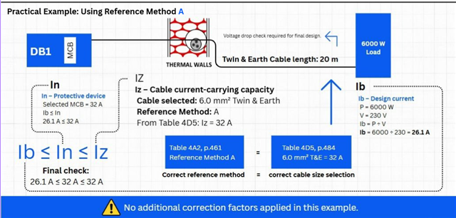
For a 6,000 W single-phase load at 230 V:
Ib = P ÷ V
Ib = 6,000 ÷ 230 = 26.1 A
A 32 A protective device is selected.
Using the relevant BS 7671 cable table for the installation conditions, a 6 mm² Twin and Earth cable installed using Reference Method A has an example current-carrying capacity of 32 A.
The design relationship is therefore:
26.1 A ≤ 32 A ≤ 32 A
The final design must also include voltage-drop calculations, correction factors, fault protection requirements and verification of the actual installation conditions.
Reference Method B
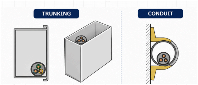
Method B applies where insulated conductors or cables are installed inside an enclosure, such as:
- Conduit
- Trunking
- A round or square box
Because the cable is enclosed, heat dissipation is more limited than with a clipped-direct installation.
Reference Method C
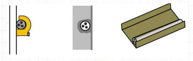
Method C applies where the cable is installed in a way that generally allows better heat dissipation, including:
- Clipped direct to a surface
- Chased into a wall
- Installed on a non-perforated cable tray
Because the cable is not fully enclosed in conduit or trunking, it can usually carry more current than under Methods A or B.
Reference Method D
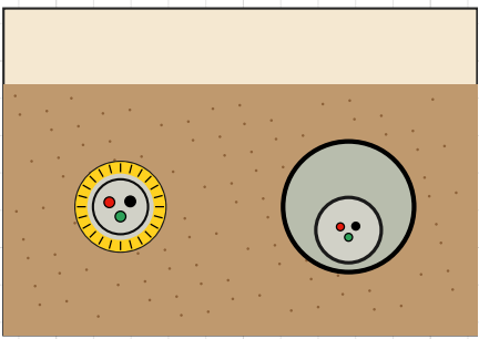
Method D applies to suitable cables installed below ground, including:
- Direct-buried SWA or armoured cable
- Cable installed in underground ducting or conduit
- Underground supplies to garages, outbuildings or external equipment
Method D is only the starting point for cable selection. The final design should also consider:
- Burial depth
- Ground temperature
- Soil thermal conditions
- Ducting
- Grouping
- Mechanical protection
- Voltage drop
Reference Method E
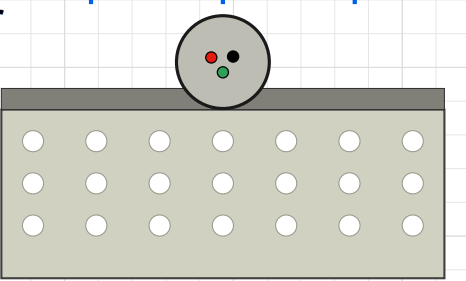
Method E applies to multicore cables installed in free air, where air can circulate around the cable.
Examples include:
- Multicore cable in free air
- Perforated cable tray
- Cable ladder
- Cleated cable with suitable ventilation
The improved air circulation usually allows greater current-carrying capacity than enclosed installation methods, subject to the relevant correction factors.
Reference Method F
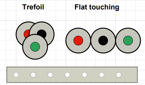
Method F applies to single-core cables touching in free air.
Common arrangements include:
- Trefoil formation
- Flat formation with cables touching
- Single-core cables installed on tray, ladder or cleats
Method F applies specifically where the single-core cables are touching. Where the cables are spaced apart, a different reference method may apply.
Summary
- Method A: Enclosed in insulation, architrave or moulding
- Method B: Installed in conduit, trunking or an enclosure
- Method C: Clipped direct, chased in or on non-perforated tray
- Method D: Direct in the ground or in underground ducting
- Method E: Multicore cable in free air
- Method F: Single-core cables touching in free air
The reference method must be established before selecting the cable current-carrying capacity from the relevant BS 7671 table.
The final cable design must also consider correction factors, voltage drop, grouping, ambient conditions, fault protection and the actual installation environment.
I prepared this as part of my continuing professional development and my work towards the City & Guilds 2346-03 Level 3 Electrotechnical Experienced Worker Qualification – Installation route.
I would appreciate any constructive technical feedback or suggestions for improvement.
Kind regards,
Mohamad Alabdallah TMIET
This is a learning summary and is not a substitute for consulting the current edition of BS 7671 and the relevant manufacturer’s instructions.

