Earth Loop Test

Our ground floor extension has 7x 12v Halogen with the necessary 240v to 12v transformers on a circuit from the wall switch. I would like to upgrade to integrated LED lamps. I understand that if I am competent, I can exchange the fittings and still be within the Building Regs rules. The new LED lamps (Collingwood H2 Lite CSP) need an earth connection.

The existing round 5A junction boxes have an in and out for the circuit (1mm twin and earth) and a feed to the transformer for each light (the transformer doesn't require an earth connection).

To verify the earth connection, I have removed the junction box and transformer for the lamp at the end of the circuit, and temporarily connected a 13A 3 pin socket and I have plugged in a KewTech Loopcheck 07. The KewTech reports all the connections are present, (so earth is connected for the circuit), but it is saying "Check loop test" because it has detected a safety earth path between 1.80 ohms and 92 ohms. 

If I plug the Kewtech into a proper 13A power circuit, it reports everything is OK.

My questions

a) Could the 240v / 12v transformers that are before the Kewtech cause an impedance issue?

b) Could one of the junction boxes have a non perfect connection and therefore cause an impedance issue?

c) Is the use of the Kewtech on a lighting circuit a valid test?

I could move the temporary 13A socket to the start of the circuit, not connect the outgoing circuit and use the Kewtech at that point. If it said everything was OK, I could work around each lamp until the Kewtech complains. 

Alternatively, I could look at a solution that doesn't need an earth connection but since the Kewtech has found an issue, it would sit in the back of my mind. 

Thank you


  • So the issue is it’s a completely inconclusive test result, maybe it is okay, maybe it’s not okay.

    British Gas giving their gas engineers testers like these created lots of work for electricians, because having got a test result they had absolutely no idea if it was acceptable or not, so they stuck a warning notice on the equipment and told the customer they needed to get an electrician to check it.

    The real answer is probably, don’t use a plug in 13-amp socket tester like this to test anything other than 13-amp sockets and definitely not a lighting circuit.

  • The real answer is probably, don’t use a plug in 13-amp socket tester like this to test anything other than 13-amp sockets and definitely not a lighting circuit.

    Agreed. As I pointed out earlier, 'quick test' socket checkers are great for peripatetic workers who work with electrical equipment plugged into standard socket-outlets, provided they are trained to use and understand their indications.

    Don't forget, even with socket-outlets, they might indicate a potential issue with socket-outlets in a perfectly fine TT system if the EFLI exceeds 90 ohms or so. 

    I don't think it's a valid method for testing earth continuity and EFLI to an extension circuit, or a replacement socket-outlet, but a quick check for correct polarity absolutely (but even then, it won't indicate a swapped L and CNE at a PME service intake equipment, that could have happened between the last EICR and the socket-outlet being replaced).

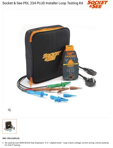
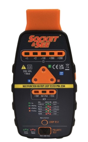
  • The Socket and See tester, as used by over 8000 British Gas engineers, has a 13-amp plug lead as well as a three wire test lead set, it also has more range indicators but there is a big difference between less than 2 ohms and less than 100 ohms, so it isn’t really more accurate.

  • Quote “The KewTech reports all the connections are present, (so earth is connected for the circuit), but it is saying "Check loop test" because it has detected a safety earth path between 1.80 ohms and 92 ohms.”.

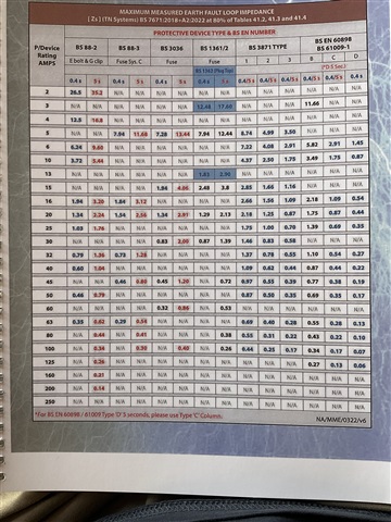
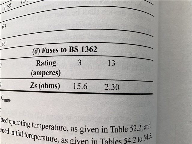
    The answer as to why the range limit is 1.80 ohms is actually fairly obvious if you think about it and have a look at the tables in BS7671 and other guidance.

    2.3 X 80%=1.84

    and it is a 13-amp socket tester.

  • The answer as to why the range limit is 1.80 ohms is actually fairly obvious if you think about it and have a look at the tables in BS7671 and other guidance.

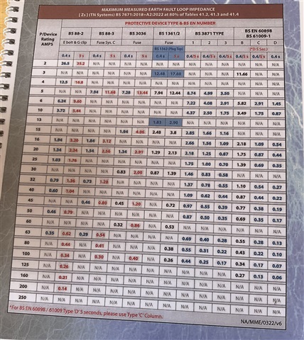
    Although I can see that, and again reinforce that for the purposes of checking whether it's relatively safe to use the socket-outlet, especially in the presence of an RCD (which the tester can also exercise, along with the test button on the device), it can't be used to verify the safety of the socket-outlet according to BS 7671 ... the 13 A fuse does not provide ADS for the socket-outlet ... the OCPD and/or RCD in the installation must do that, and for a B32, the max measured ZS is 1.09 ohms, for a B20 1.75 ohms, or a B16 2.19 ohms (or 30 mA RCD, provided it's suitable for use for ADS if voltage-dependent, the EFLI is of course much higher).

    Do not forget that, for most single and twin BS 1363-2 socket-outlets, there is no 13 A fuse:

    • when the plug is removed; or
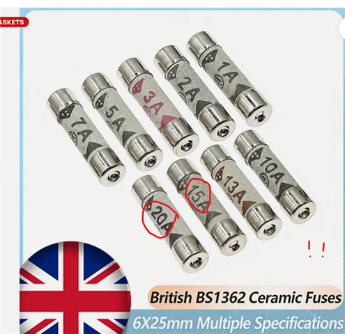
    • if someone has put a non-standard 15 A device in place of the 13 A fuse in the plug; or
    • has wrapped tin-foil around the fuse; or
    • has replaced the fuse with some studding or threads of a bolt of a similar diameter; or
    • for "wall-wart' type plug-in appliances (like the socket-tester itself)!
  • we don't know whether the circuit-breaker is  BS EN 60898 or BS 3871 Type B, or BS 3871 Type 1

    Or higher. My BS 3871 circuit-breakers were Type 3, which seems an odd choice for a domestic installation. The highest socket Zs is 1.01 Ω (at the end of a rather long spur off a ring).

    • when the plug is removed; or
    • if someone has put a non-standard 15 A device in place of the 13 A fuse in the plug; or
    • has wrapped tin-foil around the fuse; or
    • has replaced the fuse with some studding or threads of a bolt of a similar diameter; or
    • for "wall-wart' type plug-in appliances (like the socket-tester itself)!

      I see all of those apart from the last  as pretty extreme deliberate actions that are undeserving of full ADS protection, normally done by folk who really ought to know what they are doing, or arguably know better. (and you missed the re-assembly of a plug with 2 neutral pins as another common wheeze for the amateur welder ) Its not many steps away from unscrewing the socket front and wiring to the back of the thing (also seen sometimes at the shallow end).

      Wall-wart devices that are to the correct standards must include their own protection, such as thermal fuses in transformers, or deliberate weak-links in PCBs or even (god forbid) in the good ones real fuses. The fact that cheap far eastern imports exist that sometimes don't does rather undermine the safety case however.

      This sort of plug-in tester is not really meant to fully replicate the array of testgear in the professional's armoury, but is meant to warn  the handyman from using a socket or an extension lead that may appear to work but might be hiding a potentially dangerous fault. As such occasional false alarms are inevitable, and accepted as being preferable to false safe indications.
      Mike.

      PS these are a fun thing for those who enjoy the warmth of a real fire in the living room, given that a 13A plug gets pretty warm above 10A already.
      Available on a well known auction site. No, I'm not posting the link..


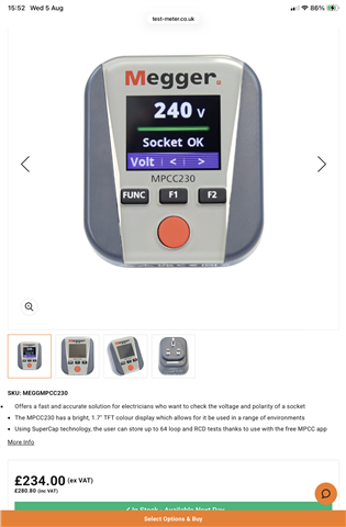
  • Even if you spend £280 on the fancy Megger socket tester, you cannot use it for certification purposes, as it cannot be calibrated.