Guidance for plug in solar for Electricians

We are now a few days from plug in solar being legal. The likes of Martin Lewis is recommending people should ask an electrician to check their installation before plugging a solar system in.

I have seen various comments referring back to changes in the law and changes to the specification for a 13A plug.

But I haven't seen any guidance from IET, NAPIT or NICEIC for electricians stating under what conditions it's acceptable to plug one of these systems in.

Personally as it stands today based on what I have seen I would not be willing to say iny installation is acceptable unless it was a single socket on it's own circuit protected by a bidirectional type A RCBO. Which I am sure isn't what the government wants.

Have I missed something, is something in the pipline?

I know lots of people will just do it, but in those situations I am not responsible.

  • “it's better to sacrifice your long nose pliers than your fingers”.

    Yes, I was advised similar, turn  it off, verify it then allow it to bleed downs and then short it out.

    (The teaching acronym was SIDE = Switch off load, Isolate supply, slow Discharge, connect to Earth)

    If you are mistaken or even just in a hurry,  but ideally if they are not your pliers, you can combine isolation,  making dead and then proving into one easy manoeuvre ! I keep some cutters with a bit missing out of the jaws that I keep to remind me not to be an idiot. 

    In a large system with lots of circuits and similar cable sizes, mistakes do occasionally occur.
     
    The London Underground have a similarly scary dead-certain process that require dropping a metal bar between the rails, before certain types of work can take place, where the instructions insist the user turns away before the bar makes contact, presumably as basting the backside of a pair of company-issue poly-cotton or flannel trousers in a shower of hot metal bits is greatly preferable to the hospital treatment for injuries to face and arms, and it is a cheap procedural habit to teach.
    Mike.

  • I fear that is partly a German to English translation issue.


    In VDE 0126 -95: 2025 as part of the testing, after removal from the supply, a  resistor of any value at least 2000 ohms is connected  back across the exposed pins of the plug, and this is listed as one of a set of actions to test that the inverter does not try to restart when there is no grid, but there may or may not be connected low current resistive loads or  worse a person in parallel.

    It does seems a bit odd to cherry pick parts of a test in this way without the rest of the explanation and other tests.

    The VDE standard stipulates that, following a grid disconnection 
    (e.g., due to a power outage or voltage faults), a photovoltaic inverter
    must continuously monitor the public grid for a period of at least
    20 to 60 seconds (with the standard setting being 40 seconds).
    The inverter is permitted to automatically reconnect
    only once the grid has remained
    (imagine this says within tolerance and - MAPJ1)
    absolutely stable throughout this period.

    Mike

  • I fear that is partly a German to English translation issue.

    The whole document appears to have been translated by AI.

    The resistor in the plug in PV to prove dead is a test as simple and as unsophisticated as shoving your long nose pliers across the pins of the plug in PV 13-amp plug when you pull it out of the socket, it should not be necessary, but it’s a very good idea as it may stop you or someone else getting injured.

    I feel sure that the resistor is part of type-testing and that there is no intention that purchasers should short out the pins every time that they remove the plug from the socket.

    What might be wise is to switch the socket off and wait a short while before removing the plug.

  • That is all very nice but what I would like to know what time it takes for the inverter output voltage to fall to zero on not seeing the grid?

    Then I can add that time to the operating time of the RCD in the  event of a circuit fault to earth to verify that is an acceptable time for protection against shock?

    JP

  • appears to have been translated by AI.

    I was being charitable - I think they could have done with a German speaker (ideally native) on the team . 

  • what I would like to know what time it takes for the inverter output voltage to fall to zero on not seeing the grid?

    Then I think we can all agree, you don't want the 40 seconds figure - that's all about not being fooled into automatically restarting too soon..


    And of course you don't really just want 'fall to zero', you need  'fall below, and stay below, a safe level'  Much as you would for oltages  generated by a washing machine motor spinning down or an SMPS with capacitors on the input. And here depending on what product standard you want to compare  to , there is a choice. 
     
    Probably the most useful in your case is 

    "The voltage at accessible plug pins shall decrease to below 34 V within 100 ms following
    disconnection from mains supply"
     
    Really though to align with BS7671, you need 50V as the touch voltage limit, but as 34 is less than 50, we can say 'faster than 100msec, but by an indeterminate amount '

    the other alternative, more use if opening covers,  is

    "Following disconnection from mains supply, capacitors larger than 100nF shall discharge to a voltage not exceeding 34 V within 1 s"


    Both of these are directly lifted from existing product standards for equipment that plugs in .

    So in the very worst case you may observe the voltage on an RCD that only just opens at  the maximum permitted 0,4 seconds after 30mA fault, with a worst case inverter plugged in, fall away to less than 50V in something under 0,5 seconds instead.
    (and indeed disconnecting a worst case washing machine mid spin cycle would be similar)

    Generally though most RCDs are a lot faster than that to open their contacts, so the real ADS situation is not as bad as that suggests.

    Mike.

  • UKSOL 460w Pro Compact Plug In Solar With Ground Mount Bundle. £849.00

    Argos 959/3202


    documents.4rgos.it/.../9593202_R_D002

  • "homes with Type AC RCDs should not use plug-in solar systems without first upgrading"

    which seems to leave homes with no RCDs at all without any constraint ... which seems a little inconsistent.

    Just read the electrical safety first document.

    https://www.electricalsafetyfirst.org.uk/safety-advice/products-and-appliances/green-energy/plug-in-solar-panels/ 

      It says 

    "we recommend households have at least a Type A bidirectional RCD protecting circuits intended for use with plug-in solar panels. Until these concerns are addressed, homes with Type AC RCDs should not use plug-in solar systems without first upgrading to a minimum Type A bidirectional RCD on those circuits."

    To me the type AC bit is just reinforcing that type AC RCD's are not acceptable, not that a consumer will be able to identify which they have.

    Which is fairly clear guidance and NICEIC have said they support the statement, I can't find anything from NAPIT other than their response to the consultation.

    So there is some documentation I can quote if I have to defend guidance I am giving. But no doubt going by the continuing divergence between NICEIC, NAPIT, IET, Electrical safety first on other issues they will come out with statements that are slightly but critically different over the next couple of months.


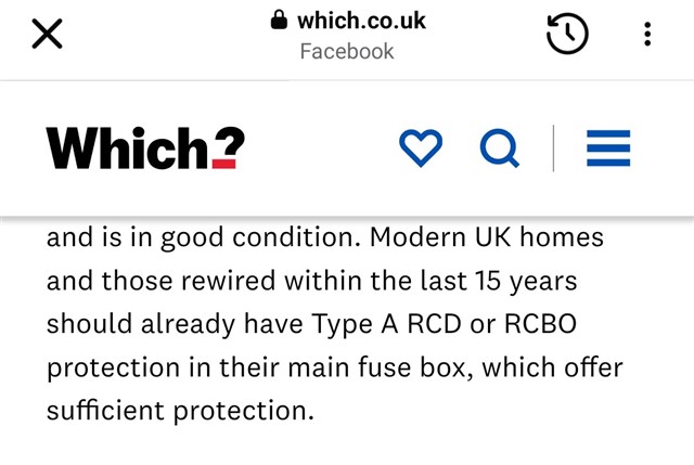
  • As seen on Facebook, Type A RCDs have been installed in the UK for the last fifteen years according to the Which magazine journalist.

  • Just read the electrical safety first document.

    How many people will do that?

    If it is important to have a bi-directional Type A RCD, then the manufacturer's instructions should state it clearly.

    Even better, the advertisements should state it so that customers do not get an unpleasant surprise.