XLPE Twin & Earth - Appendix 4 Table - Method of install

Hi there,

I have a general technical query regarding installation methods and Appendix 4 tables for Twin & Earth cables.

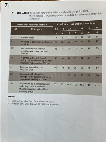
Table 4D5 is applicable to PVC/thermoplastic Twin & Earth. In this instance, with the cable installed in accordance with Reference Method 103 – within a stud wall with thermal insulation, with the insulation not touching the inner wall surface – a 2.5 mm² cable has a tabulated current-carrying capacity of approximately 13.5 A.

This can also be verified within ElectricalOM, where selecting Flat Twin 70°C PVC with CPC gives 13.5 A for 2.5 mm² under the relevant installation conditions.

However, when selecting an XLPE Flat Twin & Earth cable (90°C thermosetting), ElectricalOM identifies the cable against Table 4E2. The software also provides an option to “Run to 70°C”. When this is selected, and Reference Method A No. 3 is selected, it gives a current-carrying capacity of 21 A for 2.5 mm².

My question is therefore whether this is an appropriate application of Reference Method A No. 3 for XLPE Twin & Earth installed within a thermally insulated stud wall.

In particular, where the installation is not relying on the 90°C operating temperature of the XLPE cable, is it permissible to use the 4E2 installation/reference-method arrangement but limit the conductor operating temperature to 70°C, resulting in the 21 A rating?

Or, when XLPE Twin & Earth is installed in this type of thermally insulated construction, should the 70°C PVC/thermoplastic values from Table 4D5 be used instead, despite the cable itself being a 90°C thermosetting/XLPE cable?

The particular installation I am considering is 2.5 mm² 6242B XLPE Twin & Earth, installed within a 90 mm stud wall with approximately 50–70 mm of thermal insulation surrounding the cable. The circuit has a design current of 11.26 A and is protected by a 20 A protective device.

I would appreciate clarification on which Appendix 4 table and reference method should correctly be applied in this situation, and whether the 21 A value obtained from ElectricalOM is an appropriate basis for the cable selection.

Parents
  • A word to the wise, I would tell you to have a look in your IET Onsite Guide book, but if you bought it from Amazon it may have mistakes in it, like this one with a brown cover!

  • At least the hot running 18A 1mm2 in the bottom left (instead  I presume of 8A) is very obviously an error and unlikely not to be missed. A more subtle typo like 34 instead of 27 somewhere in the middle of the table might actually be believed by someone without a lot of experience or 'feel' for what is likely to work, and designing by relying on CAD does not help build this mental catalogue.

    It has to be remembered that the ratings in the regs, and the installation conditions and associated de-rating factors, are just (good) recommendations based on a necessarily limited no. of model test cases - real life routinely throws up situations that are not such a good fit to any of the quoted installation methods, and then engineering judgement is needed to understand what is happening, where the heat is building up and to interpolate safely and sensibly.
    Its also not static - the figures get adjusted sometimes, and additional installation cases get added to the list, so its worth keeping an eye on.

    Mike.

    As an example of even a manufacturer getting it not quite right, back when mineral insulated 'pyrotenax' was common, at one point during a copper shortage the makers suggested that a 30A ring wired in 1.5mm2 was possible - which it was, but compared to 'normal cables' the cable got remarkably hot (being copper and magnesium oxide (mineral) insulated it did not care when it got well over 100C, but the customers sometimes did !) and considerations of voltage drop made all  but the shortest run impractical. 
    Very few were installed before that advice was deleted (but the designs live on, and still work as well as they ever did, and generally don't suffer from damp in the insulation).

Reply
  • At least the hot running 18A 1mm2 in the bottom left (instead  I presume of 8A) is very obviously an error and unlikely not to be missed. A more subtle typo like 34 instead of 27 somewhere in the middle of the table might actually be believed by someone without a lot of experience or 'feel' for what is likely to work, and designing by relying on CAD does not help build this mental catalogue.

    It has to be remembered that the ratings in the regs, and the installation conditions and associated de-rating factors, are just (good) recommendations based on a necessarily limited no. of model test cases - real life routinely throws up situations that are not such a good fit to any of the quoted installation methods, and then engineering judgement is needed to understand what is happening, where the heat is building up and to interpolate safely and sensibly.
    Its also not static - the figures get adjusted sometimes, and additional installation cases get added to the list, so its worth keeping an eye on.

    Mike.

    As an example of even a manufacturer getting it not quite right, back when mineral insulated 'pyrotenax' was common, at one point during a copper shortage the makers suggested that a 30A ring wired in 1.5mm2 was possible - which it was, but compared to 'normal cables' the cable got remarkably hot (being copper and magnesium oxide (mineral) insulated it did not care when it got well over 100C, but the customers sometimes did !) and considerations of voltage drop made all  but the shortest run impractical. 
    Very few were installed before that advice was deleted (but the designs live on, and still work as well as they ever did, and generally don't suffer from damp in the insulation).

Children
No Data