This discussion is locked.
You cannot post a reply to this discussion. If you have a question start a new discussion

Mending Things

Long ago I started a thread on the maker movement and mending things:

https://engx.theiet.org/f/discussions/20498/maker-movement-mending-things

To avoid the original being broken up in ‘tree’ format I will start a new one. Maybe it will survive in a readable format.

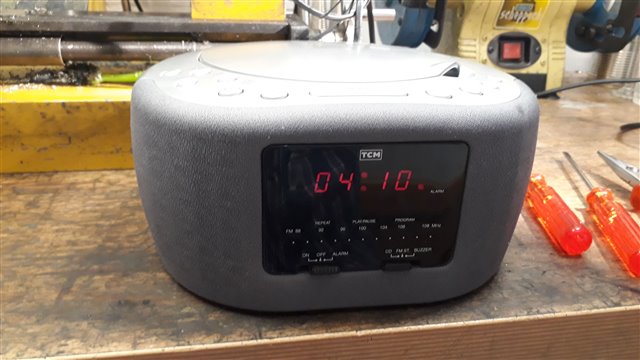
The minute set button on my 20 year old Radio/CD/Alarm Clock stopped working which made it somewhat useless. I don’t want a mobile phone by my bed so I decided to try and mend it. There were some buttons I have never used, program for example, so I hoped that the switches were identical and I could swap them.

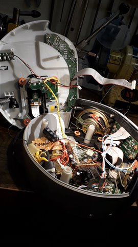
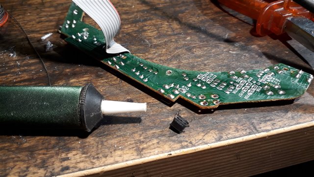
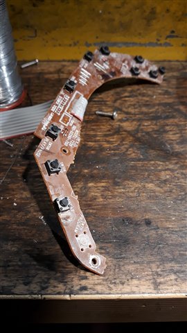
The top was held on with 3 screws. The lead for the CD Laser safety switch was very short so it had to be disconnected to get the top off. A sensible safety precaution. Four more screws and a multipin connector released the switch PCB. A quick check with a multimeter confirmed that the minute set switch was faulty and the program switch was good.

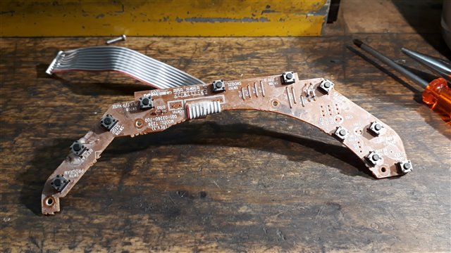
A few minutes work with a soldering iron and solder sucker and the switches were exchanged. They were also used a PCB track bridges so I couldn’t just leave one out.

Plug the cables back in, screw it back together and test. Ready for the next 20 years


  • Those little switches are flaky, I have one in front of me now, on a small PCB as part of an intruder alarm system. Sometimes it works, sometimes it doesn't, which is not good for false alarms! The alarm technician swapped the board, I put a multimeter across the switch.

    Great to see you fixed your clock, but if the problem is deeper how would you do? I have huge difficulty getting schematics for stuff (currently looking at an APC UPS - APC are very protective). I may not be able to fix a mutlilayer computer PCB, but there was a time when most gear came with a manual and a schematic (my BBC computer did). No more, but I would like the manuals/schematics to be released once the item has been "retired" by the original manufacturer - after all, if they no longer sell or support it, why not? Would give us a chance to go a little further when the problem is beyond visible and obvious. Is there a proper movement/push for this? If not I think there should be.

  • I would probably have not gone much deeper. If it was completely dead I could/would have checked the PSU components as it was a simple transformer rectifier system. To me repairing a single side PCB up to a 16 pin DIL would be possible. With a single, and sometimes a double sided PCB you can trace out the circuit in the area that you think the problem is. Multi layer PCBs and surface mount are a step too far. (I too had a BBC B complete with circuit diagram and interface specifications Grinning )

    The Right to Repair legislation should make it easier to obtain information and spare parts, but I expect there will be a few obstacles in the way.

    IET EngX (theiet.org) 

  • I am clearly in a minority then in thinking that armed with board layouts it is perfectly reasonable to grind into a multi-layer board to tap off a buried track a leayer or two in, and then fill the hole back in again with epoxy.

    Not easy,  but possible on the dining table once the wife and kids are in bed.

    the problem is the PCB layouts, and X-ray is not really a home option.

    Mike.

  • If I had the board layout I would probably attempt the same, maybe using a carbide end mill in the milling machine rather than a hand grinder. The problem as you say is getting the information. I do have to ask why you had to dig? Were the ends of the track concealed under something like a chip package?

  • I have done buried layer surgery a few times, at least once in search of a JTAG line to do something the makers never intended to be possible after leaving the factory,  in another case to fix a broken buried via, and in another to get to the memory enable lines going between two devices I did not fancy removing, both being ball grid array devices. I'm not recommending it for fun mind you, but with care and time it is possible. when you have removed enough you can see the track you want, but there is still some of the prepreg, and then manually remove that by scratching along the track length, watching under the 'scope. A rotating cutter tends to tear up the thinner tracks - often a mere 120um wide these days.

    Mike.