132/11kV transformer REF Protection frequent tripping

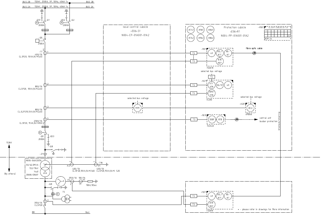
 This is an issue I've noticed all across Iraq, but I'll give you an example that I'm currently working on. We have a 132/11 kV YNd1 transformer, the primary is fed from a GIS, and secondary has a Zigzag NET with NER and a CT on the neutral point. this CT is used for REF protection.

 when we operated this transformer frequent tripping happens due to REF protection, some people say that this is due to grid instability and frequent voltage variation, others say that it's related to the current entering the neutral point due to instability. I'm not convinced by those claims and I think there's a deeper issue or reason.

 Please note that this is common around Iraq, so it might be related to the grid (in some places REF is disabled), but what I want to know is the reason behind this phenomenon.

  • HV is way outside of my comfort zone, so I probably can't be much practical help, but if I may ask a few silly question (which might even help the discussion along a bit)...

    Is this a conventional setup with the 132V side feeding the 11kV side? (i.e. conventional loads on the 11kV side, rather than backfeeding from an 11kV generator or anything like that)

    How is the transformer wired? As I read the diagram it looks to be delta on the 11kV side and star on the 132kV side - which looks the opposite way around from what I think usually happens in the UK. Is the REF CT (and NER) then between an "artificial N" point and Earth?

    sorry for the dumb questions

       - Andy.

  • In the UK the 400 and 132kV systems are generally star-wired, though the neutral is not carried on the transmission towers ('pylons')
    reference from ENW .

    However, the 33 or 11kV intermediate network transformers are delta at both ends, though the source end, much as the OP, generates a pseudo neutral by transformer, and earths it - any current in this path intended to indicate line faults on the 11kV network.

    Iraq is not my forte, and to be honest neither is this sort of HV stuff, but the two systems look comparable.

    That said some thoughts come to mind. 

    1) I assume that genuine faults on the 11kV network between lines and true earth have been ruled out ? (the kind of thing those trips are meant to catch)

    2) Are there multiple feeds into one 11kV network ?

    If so there is a current loop between the electrodes of the two transformer stations in whcih any ground currents may flow - sort of ' coming up' one NER and 'going down' the other but not actually caused by anything on the 11kV network.
    Normally in such a case there would be 'busbar blocking' logic, communicating between the two transformers, to distinguish real faults on the outbound network and out of band currents that are false alarms. mentioned here, another doc.

    3) How is the overlap or isolation of the earth electrode structures / meshes of the primary side, where random currents induced in the wires of the 132kV network may flow to ground, prevented form pulling the voltage on the 11kV earth?
    If the earth impedance is not either very low or the two earthing paths are deliberately separated,  surges on the primary side may cause  current flow in the detection transformer, again in effect coming out of the earth.

    Here I can imagine Iraq is not at all like the UK, as the earth proper will be drier and a 'good' earth connection may well be harder to achieve.

    There are others who frequent this forum who have more hands-on knowledge, and it is definitely worth waiting for them to chip in.

    Mike

  • I assume that, as well as checking for actual faults, you have verified the relay settings and any shunt / stabilising resistance required for the scheme according to the network, equipment and conditions. After a nuisance trip I would make sure to check both the calculated settings and what's actually been applied (has someone mis-set or nudged a variable resistor, for example).

    Pedantry I think, but it looks like the REF is only operating on the N-E link. I presume in practice the relay has actually got the phase CTs also (it appears the relay itself has but I don't know the device and it may be a separate input)

    The REF CTs appear to be merely 5P20. As a minimum I would normally expect class PX with a defined knee point Ukp and DC resistance Rc, although on this scale I would probably also insist that all four in a set were the same make & model, or at least pay close attention to the IV curves. It may be then that the CTs are not sufficiently linear, particularly on through-faults or other out-of-zone events, causing them to operate.

    The CTs look to be single ratio but multi-tap is common. Could you have been supplied CTs with two taps without knowing and have one or more on the wrong tap? Have seen that before due to a mistake at the marshalling box.

    Is the nuisance tripping coincident with other network operations e.g. energisation of transformers elsewhere? It may be worth seeing whether your device has inrush harmonic blocking available.

    There aren't any shown on the SLD, but I assume that no-ones been clever and swapped the earthing transformer for one with an auxiliary winding for substation loads.

  • Check the relay settings (What's it current settings, try to increase and recheck transformer operation). Also check stabilizing resistor value and settings if REF is high impedance.

  • Subject: Guidance on Frequent REF Protection Tripping – 132/11 kV Transformer

    Dear Mustafa,

    Thank you for sharing the details of the frequent REF protection tripping on your 132/11 kV YNd1 transformer with Zigzag NET and NER. Based on the symptoms and the wider experience across Iraq, I believe the issue is not simply “grid instability” but relates to the REF scheme design and settings.

    To help stabilize the protection, I recommend the following structured checks:

    1. CTs (Current Transformers)

    • Verify that all CTs (phase and neutral) are class PX or equivalent, with adequate knee point voltage and resistance.

    • Ensure all CTs are the same type and correctly tapped — mismatched CTs often cause false spill currents.

    • Perform excitation tests to confirm CTs will not saturate under maximum through‑fault conditions.

    2. Relay & Stabilizing Resistor

    • Audit relay pick‑up current and stabilizing resistor values against CT parameters.

    • Enable harmonic restraint/inrush blocking if supported by the relay.

    • Add a short intentional delay to improve stability during switching events.

    3. Earthing & Zigzag NET

    • Measure and document substation earth grid resistance; poor earthing in dry soil can allow primary surges to drive neutral current.

    • If multiple transformers feed the same 11 kV bus, implement busbar blocking logic to prevent neutral current loops.

    4. Wiring & Polarity

    • Confirm CT polarity and wiring are correct.

    • Carry out primary injection tests to prove balance during external faults and correct operation for simulated internal faults.

    5. Event Correlation

    • Review trip logs to see if nuisance trips coincide with transformer energization, GIS switching, or feeder reclosures.

    • If so, adjust relay blocking or delay settings accordingly.


    Next Steps:
    I suggest preparing a commissioning checklist covering CT verification, relay settings, wiring/polarity tests, earthing measurements, and event correlation. This will allow your team to systematically eliminate causes and stabilize the REF scheme without disabling protection.

    Please let me know if you’d like me to provide a detailed test template for your site engineers to use during these checks.

    Best Regards 

    Gary R Jones 

  • Hi Mustafa

    Not my specialist subject but I read from the Network Protection and Automation Guide (available to download *) that the delta winding  /earthing transformer arrangement will cause unwanted relay operation.

    16.10 COMBINED DIFFERENTIAL AND RESTRICTED EARTH FAULT SCHEMES

    Section 16.10.1 Application [When an Earthing Transformer is Connected Within the Protected Zone

    A delta-connected winding cannot deliver any zero sequence current to an earth fault on the connected system, any current that does flow is in consequence of an earthed neutral elsewhere on the system and will have a 2-1-1 pattern of current distribution between phases. When the transformer in question represents a major power feed, the system may be earthed at that point by an earthing transformer or earthing reactor. They are frequently connected to the system, close to the main supply transformer and within the transformer protection zone. Zero sequence current that flows through the earthing transformer during system earth faults will flow through the line current transformers on this side, and, without an equivalent current in the balancing current transformers, will cause unwanted operation of the relays.

    The problem can be overcome by subtracting the appropriate component of current from the main CT output. [ continues]

    (* If of any use, the NPAG can still be downloaded at:

    https://www.gevernova.com/grid-solutions/resources?prod=paag&type=2

    https://www.gevernova.com/grid-solutions/sites/default/files/resources/products/applications/protection-automation-application-guide-v1.pdf

    or an earlier edition at

    https://www.iqytechnicalcollege.com/network-protection-and-automation-guide-book.pdf

    )

    With best regards

    David Hawkins C.Eng, M.I.E.T.