This discussion is locked.
You cannot post a reply to this discussion. If you have a question start a new discussion

What earthing arrangement is this?

Former Community Member
The supply is from a private transformer in a four core cable 3ph + n. The cable armour is earthed and connected to the MET. However there is also a green and yellow cable connected to the neutral terminal at the main isolator going back to a the transformer casing. The transformer is only 5 or 6 metres away. I think this must have been intended to make it a tncs supply but seems to me to just create parallel neutral conductors. Or is it tn-s-c-s?  I have only been able to go off visual inspection because I could not disconnect the supply..
  • Former Community Member
    0 Former Community Member

    John Peckham:

    No it is TN-S. So any bonding can be 1/2 the CSA of the earthing conductor subject to a minimum of 6mm and need not exceed 25mm.


    Have you had a change of heart then, John ?


    Regards


    OMS 
     

  • No. The OP says the installation is TN-S as per the diagram in BS 7671.  I am assuming the neutral and earth are bonded at the transformer. I am still concerned why a green/yellow is connected to neutral at the incomer?
  • 41 postings excluding this one and the OP and still we haven't got a consensus! ?

  • The BS7671 definition of PEN is simply about sharing protective and neutral conductor functions; and the definition of protective conductor functions includes connecting an earth electrode to a source neutral point.


    In my copy of BS 7671 it seems to be worded slightly differently - mentioning only "The earthed point of the source, or an artificial neutral".


    Thus the neutral (star point) of the source could be distinct from the earthed point of the source.


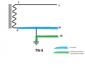
    So in my diagram:
    cb4f0ba7a2819e2221fe9e9b04dd0042-huge-tn-s-paths_zpsyci5uu0c.png


    it doesn't matter how long the conductor between the star point ("0") and the N-PE link is - it's still just a neutral conductor.


    Personally I prefer to think of protective conductors in term of the path of the consumer's connection to Earth - rather than the Earth Fault Loop - as the latter includes the conductors back to the star point - which seems to cause more than its fair share of confusion.


       - Andy,
  • Interesting to note that unlike BS7671, IS10101 does not require the PEN to be earthed at two or more points. That standard merely describes TN-C-S as a “system in which the neutral and protective conductor functions are combined in a single conductor in part of the system...”. The example figures relating to the system show two electrodes, one at source and one in the distribution but they are bracketed with the words “earthing of system through one or more earth electrodes”. So the source electrode is one such electrode. Thus what Andy has drawn would be TN-C-S if the exposed parts in the installation are connected to a separate protective conductor. Any PNB system would also be described as TN-C-S in Ireland. I am still not sure what is going on in the OP but if N and E are combined in a single conductor then it is TN-C-S. 

    The point about the length of said conductor that OMS made is very reasonable but obviously not catered for in either standard.
  • Lyle


    In the OP we have a 4 core SWA cable with a neutral inside the SWA. Parallel to this cable there is a single green/yellow. We do not know the connection arrangement at the transformer. We do know that the single green/yellow is connected to the neutral terminal at the main switch.


    I would put the earthing method down as a bodge. The OP says it is TN-S. Could the OP tell us how the cable and green/yellow are connected at the transformer end of the cable?

  • Could the OP tell us how the cable and green/yellow are connected at the transformer end of the cable?


    OP said the transformer casing - which I guess would mean the HV earth - hence a combined LV/HV earthing arrangement (cold site in old money).


       - Andy.

  • Thus what Andy has drawn would be TN-C-S if the exposed parts in the installation are connected to a separate protective conductor. Any PNB system would also be described as TN-C-S in Ireland.
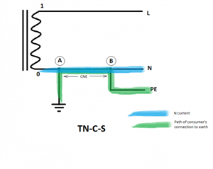


    I'm not sure that's right. TN-S vs TN-C-S and PNB vs PME are almost two different things. TN-S vs TN-C-S is about whether there's a shared neutral and earth conductor at some point in the system; PNB/PME is down to how many distinct connections to earth the N has (one vs two more).


    PNB could be either TN-S or TN-C-S depending on whether the N-PE link is upstream or downstream of the earthing of the N.

    b5d6b6dc8e4ab52c65f06dee2399d6f3-huge-tn-c-s-paths_zpshylchzz3.png


    The above would be the TN-C-S version of PNB, but add an extra electrode between A and B and it becomes PME. But the earlier diagram would be TN-S in Ireland as well I think - there being no CNE.


      - Andy.

  • AJJewsbury:

    In my copy of BS 7671 it seems to be worded slightly differently - mentioning only "The earthed point of the source, or an artificial neutral". Thus the neutral (star point) of the source could be distinct from the earthed point of the source.


    Good point. System diagrams in BS7430 suggest 'source' to be distinct from the distribution cable and the consumer terminals (where its PNB electrode is shown). But BS7671's diagrams aren't so clear as that.  Anyway: seeing it as you suggest helps avoid  the strangely broad definition of PEN. 


    it doesn't matter how long the conductor between the star point ("0") and the N-PE link is - it's still just a neutral conductor.

    Personally I prefer to think of protective conductors in term of the path of the consumer's connection to Earth - rather than the Earth Fault Loop - as the latter includes the conductors back to the star point - which seems to cause more than its fair share of confusion.


    That certainly appeals as reasonable. If I had to give a defining feature of TNCS systems and PEN conductors - in the way I still see them in spite of my surprise at BS7430 - it would be along the lines of whether a single conductor-break with only load current present (no earth fault, negligible leakage) can raise the potential of PE in the installation relative to 'remote earth'. (However, when trying in an earlier posting to see how the claim of "PNB implies TNCS" might be more reasonable than it initially seemed, I did note a couple of ways in which the PNB 'neutral' is a bit special. Its continuity does have a relevance to shock protection that's more than for just a plain load-neutral conductor, although this could be the same for some connections inside a transformer in a non-PNB system.)


  • AJJewsbury:


    Thus what Andy has drawn would be TN-C-S if the exposed parts in the installation are connected to a separate protective conductor. Any PNB system would also be described as TN-C-S in Ireland.


    I'm not sure that's right. TN-S vs TN-C-S and PNB vs PME are almost two different things. TN-S vs TN-C-S is about whether there's a shared neutral and earth conductor at some point in the system; PNB/PME is down to how many distinct connections to earth the N has (one vs two more).


    PNB could be either TN-S or TN-C-S depending on whether the N-PE link is upstream or downstream of the earthing of the N.

    b5d6b6dc8e4ab52c65f06dee2399d6f3-huge-tn-c-s-paths_zpshylchzz3.png


    The above would be the TN-C-S version of PNB, but add an extra electrode between A and B and it becomes PME. But the earlier diagram would be TN-S in Ireland as well I think - there being no CNE.


      - Andy.


    Yes, on reflection I think you are right Andy. So those diagrams in GN8 are wrong! I wonder if they do refunds!