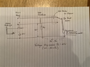
Alan Capon:Chris Pearson:
My point was that it may not be PME at all. Where are those multiple electrodes and what are they achieving?If you look at the ESQCR regulations, there only needs to be two earths to make a PME supply - one at the substation end, located at or before the connection to the first service connection, and at the far end of the PME distribution main, at or after the final service connection.
Well yes, 2 > 1 = multiple, but the reality is that we don't know where those electrodes (if any) are situated. What I don't quite understand is that if the water supply is through a metal pipe, why has it not pulled the surface potential towards the distributor's earth.
mapj1:
. . . We have a 187V potential difference between the supply neutral and house CPC, relative to the general mass of earth
Agree and note addition in bold. CPC earth is not terra-firma earth however.
in the house. If every thing Electrical in the house works that suggests the general mass of earth is rising up to 187V.
NOPE, true earth is in the right place. Relative to terra-firma Live will be falling to about 60V and neutral and CPC are at -187 such that the LN difference and CPC difference both remain 240V or what ever.
The only place there is a step voltage will be evident is near the DNO LV electrodes and again at the farm, not at the point of shock. . .
Exactly. What most are forgetting, is that a “PME Earth” is not a real Earth. The Supplier has allowed their neutral conductor to be used instead of an earth, providing certain conditions are followed, such as conductor size, bonding requirements, use only within an equipotential zone (usually taken as the walls of the main building). Everyone always quotes the “broken neutral” as the greatest risk with PME. Lyle’s scenario adequately demonstrates a much more likely scenario, and there are more scenarios that are more likely than a broken neutral, where the Supplier’s neutral conductor is displaced from being close to earth potential. You also need to consider the other two thirds of customers (assuming a three-phase transformer) where their phase conductor is 300V or more above earth potential.
Regards,
Alan.
Edited due to an over-zealous spelling checker!
Chris Pearson:
My point was that it may not be PME at all. Where are those multiple electrodes and what are they achieving?
If you look at the ESQCR regulations, there only needs to be two earths to make a PME supply - one at the substation end, located at or before the connection to the first service connection, and at the far end of the PME distribution main, at or after the final service connection.
Regards,
Alan.
Sparkingchip:
So f we install foundation earthing for an installation with a lower Ra than the DNO network earthing what happens to the touch voltages in the installation, if anything?
In normal circumstances, not a lot. During conventional L-PE faults, not too much either (the effect is still small compared with the normal metallic return path). In a broken CNE event on a PME system you'd still have 230V nominal between two different points each connected to true earth (possibly more than 230V on a 3-phase system in some peculiar circumstances) - just how that 230V (or whatever) divides between the DNO's and customer's systems will differ - the lower Ra the less the customer sees and the more the DNO's system (including N/CNE) will be affected.
To be honest I can't see it being worse than the original PME system for a CNE break near the substation where the DNO's electrode was a few tens of metres of copper buried within the substation compound while the consumers side was connected to literally miles of metallic gas and water pipes.
- Andy.
We're about to take you to the IET registration website. Don't worry though, you'll be sent straight back to the community after completing the registration.
Continue to the IET registration site