For example, 110% of 230= 253 volts. Assuming L and PE are of the same size and material, indirect contact touch voltage is 126.5 volts. Would 0.33 seconds not appear more realistic?
From IEC 61200-413

ProMbrooke:
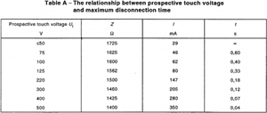
I am a bit confused by this. Why do the disconnection times in Table 41.1 appear to be based on a touch voltage of 100 volts rather than a touch voltage of 125 volts?
For example, 110% of 230= 253 volts. Assuming L and PE are of the same size and material, indirect contact touch voltage is 126.5 volts. Would 0.33 seconds not appear more realistic?
From IEC 61200-413
Table 41.1 refers to MAXIMUM disconnection times.
NOTE 1 says that disconnection is not required for protection against electric shock, but may be required for other reasons such as protection against thermal effects. Also, a 30mA R.C.D. usually protects against dangerous electric shocks in most cases, due to its swift operating action.
Z.

Zoomup:ProMbrooke:
I am a bit confused by this. Why do the disconnection times in Table 41.1 appear to be based on a touch voltage of 100 volts rather than a touch voltage of 125 volts?
For example, 110% of 230= 253 volts. Assuming L and PE are of the same size and material, indirect contact touch voltage is 126.5 volts. Would 0.33 seconds not appear more realistic?
From IEC 61200-413Table 41.1 refers to MAXIMUM disconnection times.
NOTE 1 says that disconnection is not required for protection against electric shock, but may be required for other reasons such as protection against thermal effects. Also, a 30mA R.C.D. usually protects against dangerous electric shocks in most cases, due to its swift operating action.
Z.
Right.
Note 1 only applies to DC touch voltages between 50 and 120 volts.
RCDs can and do fail and should not be sole means of achieving ADS.
AJJewsbury:
I suspect it's a mix of history and standardization with a bit of finger in the air approximation thrown in. I believe that 0.4s was agreed on for continental 220V supplies (110V touch voltage if equal sized line/c.p.c.) and we in (then) 240V land adopted the same - arguing that our per-installation bonding would likely reduce the touch voltage inside the building to well below 110V levels. There's a similar argument for permitting reduced c.s.a. c.p.c.s. which otherwise can similarly result in higher touch voltages. Portable equipment outdoors should be covered by a 30mA RCD so have a faster disconnection time anyway.
There are so many unknowns - body resistance, resistance of contact with the general mass of the earth, actual supply voltage, droop in supply voltage due to the short circuit that occurs during a L-PE fault on a TN system, exact effect of main bonding, not to mention variation between individuals - that it's far from being an exact science. There's likely some approximation gone into that table above - nice round whole numbers seem rather unlikely for real life.
- Andy.
I'd say so by the looks of it.
The thing is I'd assume worse case scenerios would be observed which IMO are both reasonable and predictable. For example, faults on 32 amp and under circuits are not likely to cause much if any voltage droop on the output of the DNO transformer (16 x 7= 112 amps on a 500kva unit where 700 amps per phase is norm), +105-110% voltage is within bounds, the majority of the voltage division is among the final circuit whereby the few voltages drop across the incoming PEN make little difference in contact voltage when the PEN is bonded to all exposed metal, contact with remote earth is not unreasonable if outside, ect.
However, I do agree with you on body resistance and footwear as it can range dramatically. But considering children, the elderly, ect assuming a 5% of the population number I think is fair.
Zoomup:
If they are not totally reliable then use two in series to half the perceived risk.
No, it's much better than that. Assuming that whatever causes one to fail does not affect the other one, i.e. failures are independent of each other, the risk is squared. So if the failure rate of one is 7% (about 1:14) the failure rate of both is 0.5% (1:200).
Chris Pearson:Zoomup:
If they are not totally reliable then use two in series to half the perceived risk.No, it's much better than that. Assuming that whatever causes one to fail does not affect the other one, i.e. failures are independent of each other, the risk is squared. So if the failure rate of one is 7% (about 1:14) the failure rate of both is 0.5% (1:200).
Oh ek! I knew that I should have gone to those maths' evening classes.
Z.
Zoomup:
R.C.D.s have saved many lives. If they are not totally reliable then use two in series to half the perceived risk. Are M.C.B.s a hundred per cent reliable?
Z.
Why can't the MCB be the backup? A series RCD would either have to be in literal series, or a delayed trip type main with a higher ma threshold.
We're about to take you to the IET registration website. Don't worry though, you'll be sent straight back to the community after completing the registration.
Continue to the IET registration site