Why don' we use RCD trip times for adiabatic equation

When using adiabatic equation for calculating minimum size of CPC, every example I have seen uses 0.1 second or whatever the disconnect time of the mcb element of the RCBO  or MCB will be.

In a domestic sittuation most circuits are protected by RCD's with a trip time of 40mS with significant fault currents, in this sittuation why don't we use 40mS as T in the adiabatic equation?
Parents
  • Quite simply because adiabatic is about protection against overcurrent, and RCCBs, or the RCD element of a combination protective device, cannot provide protection against overcurrent.

    GN6 tells us (Section 1.5):

    While residual current devices (RCDs) can provide protection against electric shock by automatic disconnection of supply, they do not provide protection against overcurrent. Residual current circuit-breakers (RCCBs) must always be backed up by a separate overcurrent protective device to protect against fault current (and, if required for the particular circuit, overload current). Overcurrent protection may be included in the same device, for example, residual-current circuit-breaker (with overcurrent protection) (RCBO).

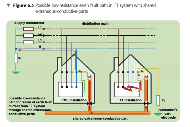
    This does bring into question how we approach the situation for TT systems. The important factor is that we can't assume the prospective earth fault current is determined by the earth electrode alone (in the way we do for ZS for ADS), because extraneous-conductive-parts, or fortuitous earthing, may well reduce the overall effective earth electrode resistance ... and increase prospective fault current.

    In the worst-case, prospective earth fault current could well be the same as L-N prospective fault current (see Section 6.4.3 of GN6), and therefore we ought to consider using the same approach for protection against overcurrent for earth faults in TT system earth faults, as TN system.

  • thought that not all FAULT currents are necessarily OVERcurrents

    Correct. There are cases even in faults between live conductors, a specific OCPD is not required because of the nature of the source of supply.

    if you have a TT supply with a line to exposed-conductive-part fault, the fault current isn’t necessarily going to exceed the rated value of the cable as it may only be a few amps

    This is where things start to get tricky. For ADS, we are required to consider worst-case conditions, which are taken to be the highest resistance of consumer's earth electrode, highest Ze from the distributor's supply, and NO parallel paths.

    However, in a real fault to Earth, for protection against overcurrent, you need to take into account the highest prospective fault current, not lowest Zs. In a real installation, you will have parallel paths, and potentially a much lower resistance of consumer earth electrode. Worst case is the example shown in GN6 and EIDG, which shows a TT supply from a PME system, with shared extraneous-conductive-parts. Here, the prospective fault current is practically that of the TN system next door, but you can't rely on that for ADS ... see Figure 6.3 of GN6 9th Ed 2022

    A short to an exposed conductive part is a Fault. Such a fault can be protected against by an RCD (and usually more slowly by an OCPD).

    Only for protection against electric shock, as discussed above.

    This is where Table 41.xx won't help - because they are to achieve ADS.

    You may also need to take into account the backup protection of the RCD, as the real prospective fault current (which varies throughout the year) will be higher than that values you used in calculating Zs for ADS in Chapter 41.

  • if you have a TT supply with a line to exposed-conductive-part fault, the fault current isn’t necessarily going to exceed the rated value of the cable as it may only be a few amps, and so would not meet the definition of an Overcurrent.

    Or another approach - the definition is about the current exceeding the "rated current" - with a cable's CCC is only one example (the rated current of a conductor). There are other considerations too which you might have to consider when deciding that the rated current for a given situation is. For instance a c.p.c, or indeed the earthing system in general, will naturally develop a potential difference between its ends when carrying a current - if that exceeds some limit (say 50V) then safety is compromised regardless of whether the conductors start to overheat or not.  So you might decide that the maximum intended (or "rated") current that an earthing system can carry indefinitely  is substantially less than the CCC of the conductors that it consists of.

       - Andy.

  • Graham (and AJJewsbury),

    Thanks very much for the feedback. The comment above regarding “in a real fault to Earth, for protection against overcurrent, you need to take into account the highest prospective fault current, not lowest Zs”, leads nicely in to the main query I wanted to ask on this thread:

    I have a situation where a number of rural roadside technology cabinet sites were designed to be supplied by a TN-C-S DNO supply, but are now, at time of installation, to change to TT following further DNO feedback. When I update the design to reflect the alternative means of earthing, the smaller cables are failing the Adiabatic / Energy let-through calculation, and I can't change most of the elements as I have to work within the constraints of the client’s equipment, as summarised below:

    Adiabatic Check:

    K = 115 (can’t change, roadside cabinet is supplied by client to their own specification)

    S = 0.75mm2 (can’t change, roadside cabinet is supplied by client to their own specification)

    I = 11A (TT earth electrodes have been specified to be max 20 Ohms. It may be possible to achieve less to get a slightly higher fault current, but no guarantee)

    OCPD: Schrack RCBO C6 30mA, type A, 6kA (backed-up by a 40A BS88-2 fuse) (can’t change, roadside is cabinet supplied by client to their own specification)

    t = would need to be <= 62.3s to satisfy the Adiabatic equation. Fig 3A5 indicates a time of over 400 seconds for the OCPD = Fail


    Energy Let Through Check:

    The cable withstand (K2S2) value is less than the energy let through (I2t) of the OCPD in EIDG table 8.6 = fail

    I appreciate that the I2t values in table 8.6 are ‘generic’ and that manufacturer specific values are usually less, which may help my situation.

    However, I have contacted the OCPD manufacturer, Schrack, and they have responded to say that they cannot provide such values (and their datasheet does not go any lower than 500A), and advised me to refer to IEC/EN 60898 for the maximum allowed I²t values – which effectively points me back to the generic/high values in EIDG table 8.6. So I am a little stuck.

    Refs in GN6 6.4.3 and EIDG 8.11 reiterate what you have said about considering the highest prospective fault current. The original calculations were done assuming a TN-C-S supply with prospective fault current of 16kA and Ze of 0.35, and there was no problem. It is only after switching the supply type to a TT that the Energy let through issue has arisen. Does the fact that the design worked fine for a 16kA, 0.35 Ze TN-C-S arrangement not provide sufficient evidence that the design is compliant for the potential worst case fault current under a TT arrangement?

    The referenced sections in GN6 6.4.3 and EIDG 8.11 don’t appear to mention any concerns over the prospective fault current being too low for an RCD, only too high, so could we not be satisfied that the RCD would be tripped by the 11A earth fault current, and any higher fault currents would be tripped by the overcurrent protection in the MCB element of the RCBO (as it has been proved in a TN-C-S equivalent calculation of the same design)?

  • I appreciate that the I2t values in table 8.6 are ‘generic’ and that manufacturer specific values are usually less, which may help my situation.

    However, I have contacted the OCPD manufacturer, Schrack, and they have responded to say that they cannot provide such values (and their datasheet does not go any lower than 500A), and advised me to refer to IEC/EN 60898 for the maximum allowed I²t values – which effectively points me back to the generic/high values in EIDG table 8.6. So I am a little stuck.

    I can appreciate your difficulty here. Some manufacturers publish plenty of data; others less. As you say, the BS EN 60898 values are maxima. I think that you need to persevere - Schrack must have tested their devices otherwise they could not claim compliance with BS EN 60898.

  • I = 11A (TT earth electrodes have been specified to be max 20 Ohms. It may be possible to achieve less to get a slightly higher fault current, but no guarantee)

    Herein lies the problem ... you may well have a different prospective fault current.


    However, I have contacted the OCPD manufacturer, Schrack, and they have responded to say that they cannot provide such values (and their datasheet does not go any lower than 500A), and advised me to refer to IEC/EN 60898 for the maximum allowed I²t values – which effectively points me back to the generic/high values in EIDG table 8.6. So I am a little stuck.

    Agreed - so what is protecting the 0.75 sq mm?

    This is where I think you need to use adiabatic over the RCBO curve, because as the manufacturer says, the IEC/EN 60898 for the maximum allowed I²t values (or manufacturer's stated values) are only where the disconnection time is very short, i.e. for the "instantaneous trip" values, or t < 0.1 s (see second para of Reg 434.5.2 of BS 7671). That would cover you for high prospective fault current.

    When we talk about trip times > 0.1 s, you need to plot the csa over the generic mcb curve in Appendix 3 (Fiig 3A4 for Type B)

    This would appear to show that a B6 is unable to protect 0.75 sq mm cable unless you can achieve "instantaneous tripping").

    HOWEVER, that's not the end of the matter ... I'm fairly certain that if you do a non-adiabatic line plot using the method in BS 7454 against the curve against the B6 curve, you will be able to demonstrate that the B6 always protects the 0.75 sq mm cable. Quite simply, it has to, because 0.75 sq mm copper generally has a basic current-carrying capacity of 6 A.

    S = 0.75mm2 (can’t change, roadside cabinet is supplied by client to their own specification)

    Is that specification also requiring you to conform to BS 7671? 0;.75 sq mm is only permitted (Table 52.3) for specific appliances (per the product standard) or in cables with seven or more cores

  • It is a very well lagged 0,75mm cable that cannot take 11 amps pretty much forever. !!  The adiabatic approximation turns to dust for long time duration, as it assumes the heating is all over so quickly no heat leaves the copper core of the cable. It is often stated to be valid for 5 seconds or less - even this is a horrible kludge, as the time constant depends on the cable size.

    For example,  a chunk of 16mm2 will have a time constant of many tens of seconds, while your 0.75mm2 probably starts to get at least heat into the PVC jacket and on its way off to the outside world, within  a couple of seconds...

    In any case, with 60 odd seconds, you are using  the adiabatic approximation in  a region where it is not the most appropriate method.

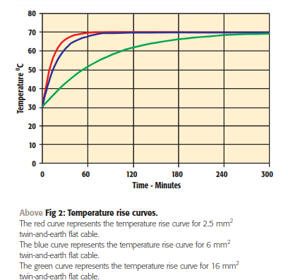
    (a 1mm core in PVC insulated T and E or round flex in free air is good for 11A with an eventual 40C rise At the same current, 0.75mm2 will see a temperature rise of  4/3 as much, so about 54 degrees. Assuming a 30C ambient, that is a touch under 85C on cable intended for 70C )

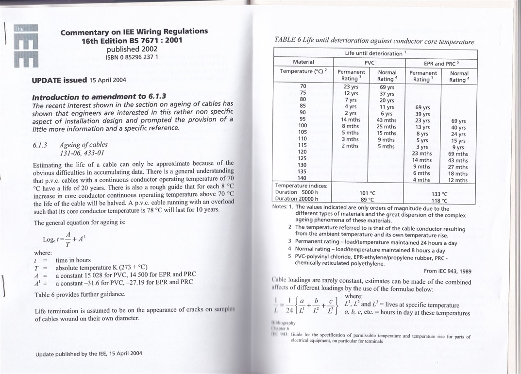
    A quick look at accelerated ageing data suggests you will really have several years at 11A to operate the MCB before the cable is significantly damaged.....

    If you had higher fault currents and trip times of few seconds or less really, then you would want to invoke the adiabatic equation, but by then the MCB has got out of bed, yawned, stretched and is actually reacting pretty promptly.,,,

    Hope this is reassuring.

    Mike

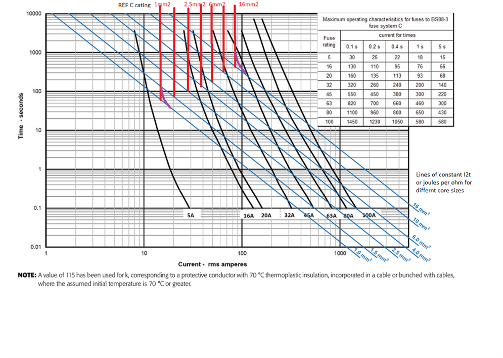
    PS, for cable, as for fusewire, you can create a composite curve of current versus how fast the ADS must operate, The cable continuous rating forms a vertical line, here in red, as currents at or below that are OK for infinite time duration operation (well decades) . Then as the current goes up, so the permissible duration comes down  - at the very high current end of things,  the times are short, and set by a 'constant energy' situation, here in blue as there is no cooling, In between one can create intermediate points using data like that in the accelerated aging data above, or shown in purple in this graph, the eye of faith...

    These previous discussion threads may help explain that better.

     Adiabatic plots 

     Cable Sizing based on I2T - 5 second boundary 

    Note that the onset of some cooling is far faster than the final time to reach steady state temperatures - curve below  from (https://electrical.theiet.org/media/1704/establishing-current-ratings-for-cables-in-thermal-insulation.pdf ) suggests tens of minutes. Again, you have ages before anything  gets even slightly near dangerously hot,

  • This would appear to show that a B6 is unable to protect 0.75 sq mm cable unless you can achieve "instantaneous tripping").

    Unless you go down the 435.1 route - In ≥ Iz so overload protection is provided, and as long as the breaking capacity is suitable, fault protection may be assumed.

        - Andy.

  • In ≥ Iz so overload protection is provided,

    Yes, with the important caveat being that would only work if there are no de-rating factors to apply to the 0.75 sq mm conductors, because Iz is the current-carrying capacity in the given installation conditions. (Hopefully, the cable is suitable for 6 A in the given conditions in this particular case, but there may well be cases where protection against overload by other means, or where overload protection can legitimately be omitted.)

  • I've lost count of the number of EICRs I've seen where the testers have failed 1mm lighting circuits that are protected by a 16A MCB.  

    It would be interesting to see a general justification for 16A MCBs protecting 1.0mm² conductors for faults - 434.5.2 points us to confirming that I²t ≤ k²S². A PVC insulated conductor typically has k=115 so 1mm² has a withstand (k²S²) of 13,225 A²s. Compare that with BS EN 60898's generic values for energy let-through (I²t) for a B16 of 15,000 A²s at 3kA, rising to 35,000 at 6kA (or 18,000 rising to 42,000 for a C16).

    For a B6 (or C6), as In ≤ Iz we can at least use 435.1 to deem it OK (presuming the MCB has the required breaking capacity).

    Some MCB manufacturers publish their own lower figures for energy let-though, which may tip the balance in your favour in specific cases of course, but that's a long way from being able to make a blanket statement of suitability.

       - Andy.

  • Indeed, though a lot depends on the type of wiring. For identically sized conductors, table 54.7 can be used to determine suitability without even needing to do an adiabatic. Would be difficult to state that the circuit wasn't compliant, especially if 433.3.1 was applied. 

Reply
  • Indeed, though a lot depends on the type of wiring. For identically sized conductors, table 54.7 can be used to determine suitability without even needing to do an adiabatic. Would be difficult to state that the circuit wasn't compliant, especially if 433.3.1 was applied. 

Children
  • For identically sized conductors, table 54.7 can be used to determine suitability without even needing to do an adiabatic.

    Only for c.p.c.s - you still have the problem of proving that a 16A MCB protects the 1.0mm² live conductors against faults.

      - Andy.