When parts are not Exposed-conductive parts

BS7671

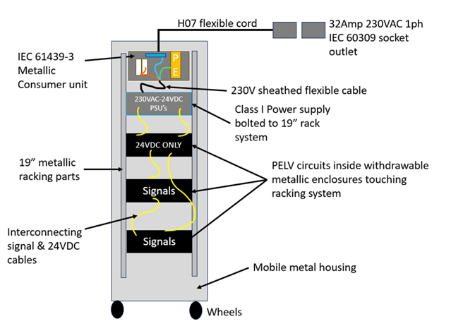
A mobile 19” racking enclosure containing a number of withdrawable LV class I items of equipment and other ELV measuring circuits contained within metal enclosures - the overall mobile racking unit is on wheels and floating from earth – however, the metal parts are only in contact with earth via the class I items located within it.

just considering protective systems and not EMC,  I would instinctively say that the entire mobile unit and its mechanical elements eg vertical struts, doors and outer enclosure form part of the ‘installation’ . All conductive parts which could become live under single fault of one of the class I items, so therfore all conductive  parts of the mobile unit ought to be bonded to its incoming supply earth terminal giving consideration to regulation 543.

But is it wrong to classify the racking system as exposed-conductive parts? Does the definition of exposed-conductive not extend to the racking it is bolted to?

Instead, does the racking qualify as extraneous-conductive parts which needs to comply with regulation 544 i.e. Bonded to the earthing terminal within the mobile enclosure with green/yellow not less than 6mm or half the CSA of the line conductors of the building’s incoming supply?

In summary, should I be bonding the racking parts via regulation 543, 544 or not bond at all?

Thanks

  • It depends if the rack is an appliance with one mains lead, or more like a set of shelves that happen to be metal, that kit is sitting on...

    In neither case is it exactly a fixed installation as per BS 7671 but the principles are similar. Does the rack include distribution -  a fixed 4 gang extension lead  for example? In your case a clear yes - you show a mini CU.

    If so good practice would be to earth the rack - and to be aware of earth leakage - if the whole rack is on one mains lead and the CPC failed how much total CPC current would be available to shock someone touching the rack ? If that is single fault to danger then provision for a secondary bond of the rack to supply earth may be needed,.

    Mike.

  • But is it wrong to classify the racking system as exposed-conductive parts?

    If all mains-powered products within the enclosure are self-contained Class I or Class II, and all wiring is insulated and sheathed, then, according to BS 7671, strictly, yes the metal parts of the "rack" are not exposed-conductive-parts. And usually, neither are they extraneous-conductive-parts.

    There are, however, very good reasons to provide supplementary protective bonding for safety purposes, including:

    • High protective conductor currents - helps reduce risks for anyone maintaining equipment in the rack.
    • Provides additional protection, which could be used as one of the mitigation measures if a risk assessment is used to omit RCDs for socket-outlets rated < 32 A (Regulation 411.3.3).
    • Could be considered a "restrictive access" location when someone is working in it, so if a fault to Earth occurs, bonding helps reduce risk of effects of shock.
    • If there is a lot of data cabling coming out of the rack, especially long runs, this picks up induced current which can also be a hazard. Screens of such cable may be bonded elsewhere, so the bonding in the rack helps to prevent touch-voltages between telecomms cable screens and local "earthy" things (this can, under certain circumstances, in very large premises, or with external cabling, be lethal to anyone working in the rack, if not handled correctly).

    However, as you pointed out, the main purpose of bonding is as an EMC mitigation measure, for which purpose low inductance bonding is required (and multiple bonds help reduce inductance). The requirements for bonding in telecomms racks are not in BS 7671, but in BS EN 50310 (IEC 30129 internationally). Section 444 of BS 7671 refers to BS EN 50310 for this purpose.

  • It is the latter of several appliances that happen to be sitting on metal shelves - the complete mobile enclosure isn’t a product / appliance in its own right (well at least that’s my interpretation). 
    yes there will also be a multi-gang power distribution extension unit with IEC C13 type connectors

    ultimately the whole rack is fed from one supply inlet via a 6mm2 flexible cable with a 60309 plug. I don’t yet know what the earth leakage is, but my understanding around 543.7.1.202 is that my supply cable/connector is adequate. As for the internal equipment take your point and make sure these have secondary bonding if necessery - on a Sadie note, some class I devices have an earth stud on the rear panel  - is the purpose of these studs specifically for that leakage reason? Allowing a secondary bond or are they more EMC related?  

  • Will there be a UPS at the bottum of that rack?  How heavy are the PSUs?

    It is best practice to put the heavier kit at the buttom of the rack, it makes it more stable and less likely to topel over when someone slides any of the kit out and thus causing an imbalance.  The UPS (Uniturrupted Power Supply) will do several things.  Provide power for a set amount of time on power supply lose, clean the power coming into the unit.  Personally I always recommend a UPS on all racks.  The cost is an informed decission the customer has to make. 

    Back in the day when dealing with sound or comms equipment they would use smal length cables at the front of unit in yellow or yellow green connected to each peace of kit in the rack.  You would see then daisy chain from U1 to U47.  This was to help get rid of or disapate static it also helped to earth the cases of the kit should there be a fault .  These day people would call it some kind equipotential bonding.  If this was not done SOME kit would transfer that energy/static into the kit and cables.  This would result in hiss or static or crackle on the device like a phone or a speaker.  All of that bonding/Earth/equipotention stuff would then be connected to Earth.  Some people would call it a CLEAN EARTH.  Not sure how they cleaned it maybe with soap or something.  (poor humour)  Normally this Clean Earth got connected to a Earth rod and was separate for the rest of the instal Earth.  As a side not when you disconnect the power for this unit after it has been runnning for a while don't touch the Earth pin on the plug.  They get incredible hot due to intentional earth leakage of the DC equipment.  Another point to conside is the flooring, if it is carpet which will probably have a high nylon content it will build up staic as people walk over it you will then find engineers get staic shocks when the touch the metal kit or racking. 

  • Normally this Clean Earth got connected to a Earth rod and was separate for the rest of the instal Earth. 

    And the way many of those installations were carried out might now be considered unsafe - the "clean earth" system must be bonded to the mains Earth at least at one point, but there are other requirements in BS 7671 regarding the cpc needing to be installed to each point in wiring.

    These days, it's quire clear that Functional Earth (FE ... now coloured pink) has NO protective function.

    If the conductor is a combined protective and functional earth (CPFE) then it's green-and-yellow, and the requirements for protective earthing (PE) take precedence. BS EN 50310 (IEC 30129) contains an approach that is used to "clean up" the PE system so it's more suited for use by electronic systems, and separating sub-mains and final DBs for "noisy" and "victim" equipment is also recommended.

  • It is common to add earth studs of the back of kit that either has higher thna normal earth leakage, and needs additional high reliability CPC back to the supply, or to allow bonding to othe bits of kit as an earth loop mitigation.

    'Clean earths' are a bit of a misnomer, and really mean not sharing the CPC with something that is injecting large currents into the CPC, to ensure that there is not a large voltage difference between parts that are nominally earthed to the same thing, but not via  short route  to each other. It is very rarely the earth resistance that matters, but the micro-henry or so per metre that the wiring introduces  

    V=L*di/dt

    and all that.

    'The earth' voltage as a constant equipotential in space-time makes sense at 50Hz on an installations up to a some km across at least. The same idea does not extend well to microsecond pulses from motor  brushes etc.

    It is much better to consider 'earth'  more like a local 'level' but level like the deck of a ship - free to bob up and down relative to other decks on other boats  ( ie. an indeterminate and changing offset voltage relative to 'earth' in other equipment) or to the general land mass far away.

    Long earth leads are your mooring ropes, and the voltage gradient along them may slope up or down depending what is happening at each end.

    Mike.

  • Normally this Clean Earth got connected to a Earth rod and was separate for the rest of the instal Earth

    It shouldn't have been - even in the old days everything in reach of eachother had to be on the same earthing system. "Clean earths" were usually implemented by connecting back directly to the building's MET - the idea was to avoid what we'd now call protective conductor currents (both from normal operation and during fault) from elsewhere in the installation. One of the problems they were trying to avoid was due to data/signalling systems of the time (RS 232 etc) often used earth as a return/reference wire - so a few volts difference in the PE potential on interconnected equipment could show up as digital 1s instead of 0s (or vice versa).  These days we tend to go the other way and try to mesh things together to reduce the voltage differences by minimising the impedance (rather than minimising the current). It's helped that most modern data signalling these days are differential, so are much less affected by small differences in local PE potentials.

       - Andy.