Touch voltage

Hello

I have a basic question on touch voltage. I just can't seem to grasp it..
This is taken from guidance note 5
I have attached 3 sketches alongside .

1 and 2 are as GN5 describes

The third is my confusion.

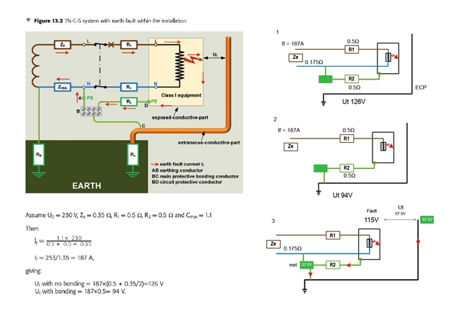
1 & 2. We calculated touch voltage, in this case 126V without MPB and 94V with MPB

Now I understand I think the basic concept the greater the resistance , the higher the voltage current being constant

Number 3, is How I imagine it...
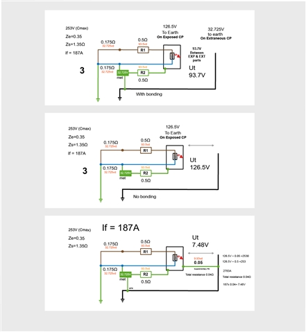
We have a fault and at the Exposed CP we have a voltage of say 115V
The resistance of the CPC to the MET will reduce this voltage again to say half again so 57.5V at the MET

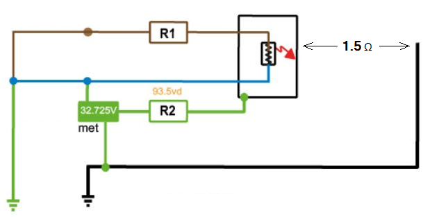
Since we have MPB connected to the MET . The MET and Extraneous part will be  roughly at 57.5V

So our touch voltage would be between the EXP and EXT conductive part so.115V   ----   57.5V   A difference of  57.5V

I don't understand in the GN5 examples, Why is  touch voltage is one amount?
126 volts to what?  To Earth? 
But since the MET will be at a raised potential It can't be to earth?

Hope that makes sense.


  • Thanks all 


  • I think I have it now as in the first 2 pics

    In the 3rd I have tried to calculate touch voltage with supplementary bonding in place.
    Im I in the right area?

    Thanks very much

  • I used the 126.5V as a constant voltage?

  • Im I in the right area?

    More or less, except that -

    the Zs will be reduced by the SB being fitted, and 

    not quite all of the fault current will flow through the SB; a (small) part of it will flow through R2.

    So Ut = If (in SB) x 0.05

  • Also, with reference to the formula R≤50/Ia as stated in the regulations:

    It is not the resistance between exposed and extraneous-c-ps which is the relevant value for touch voltage but, as in the above examples, solely the resistance of the SB. The resistance of the extraneous-c-p between touch point and SB connection is irrelevant.

  • I used the 126.5V as a constant voltage?

    Probably safer to use 230V (x1.1 if you like = 253V) across the entire loop - 126.5V is based on the assumption that the L and PE sides have the same impedance - which may be true if you have equal sized L and PE or PEN conductors - but having a supplementary bond undermines that assumption (as does using some common cable types, e.g. T&E which have a reduced c.p.c.s).

       - Andy.

  • This is really helpful thank you. I promise not to keep bothering you.


    Just on the Supplementary though..

    So Ut = If (in SB) x 0.05

    the supplementary bond is in effect parallel with the c.p.c - which reduces the overall earth fault loop impedance, and so increases the fault current

    So calculation of the  new Zs is needed

     253V

    0.05Ω SB and 0.5Ω R2 in parallel = 0.05Ω

    plus R1 0.5

    + Ze 0.35Ω

    Zs 0.5+0.05+0.35 =0.9

    253 / 0.9 = 281.1A

    281 x 0.05 = 14.05V

    So without bonding we had  Ut = 126.5V
    With bonding Ut = 93.7V

    With Supplementary  = 14.05V?

    Thank you


  • Nearly -

    With a fault current of 281.1A flowing through the CPC of 0.5Ω and SB/pipe/MEB of  0.05Ω (say negligible for pipe and MEB) then 90% of the fault current will flow through the SB; i.e. 253A.

    So Ut = 253 x 0.05 = 12.65V

  • Just on the Supplementary though..

    So Ut = If (in SB) x 0.05

    the supplementary bond is in effect parallel with the c.p.c - which reduces the overall earth fault loop impedance, and so increases the fault current

    No, I disagree with the 'supplementary bond is in effect parallel with the cpc' in all cases. The resistance cpc's of the circuits alone (R2 of circuit 1 + R2 of circuit 2) may be of sufficiently low resistance to a common DB earth terminal (or in a smaller installation, all the way back to MET) to meet the requirements of Regulation 415.2, especially if RCDs are used. And, see 544.2.1, protective conductors in sheathed cables, or in conduit or trunking, mean the minimum csa can be less than 4 sq mm; the only issue is if there's a disparity in cpc csa between the circuits ... you'd have to reinforce the smaller one with a conductor of csa not less than the largest of the cpc's.

    Also, highlights the fact that 415.2 does not necessarily reduce touch-voltage. It 'reduces touch-voltage to 50 V AC or 120 V DC or less for currents that will not operate the relevant overcurrent protective device in 5 s, or alternatively the relevant RCD in either 0.3 s (for non time-delayed devices) or 0.5 s (for S time-delay devices).'

    If the fault current is more than Ia, the touch-voltage may well be > (or even >>) 50 V AC or 120 V DC, but will be disconnected in a known time.

    Look closely at the formulae in 415.2.2:

    415.2.2 The resistance R between simultaneously accessible exposed-conductive-parts and extraneous-conductive-parts shall fulfil the following condition:

    R ≤ 50 V/Ia in AC systems

    R ≤ 120 V/Ia in DC systems

    where Ia is the operating current in amperes (A) of the protective device or:

    (i) for RCDs, IΔn

    (ii) for overcurrent devices, the 5 s operating current.

    Nothing in BS 7671 limits touch-voltages absolutely in all possible fault conditions, except SELV (and even then, caution if you choose certain modern electronic sources, because they don't all conform to 414.1.1 with respect to voltage limits in certain Sections in Part 7).

  • If this exposed to extraneous-c-p resistance happens to be 1.5Ω on a 6A circuit where R<50/Ia is 1.67Ω,

    how does that have any bearing on touch voltage?