This discussion has been locked.
You can no longer post new replies to this discussion. If you have a question you can start a new discussion

530kW motor checks? !!

Former Community Member
Hello to all, and I do hope that people can advise me on this?


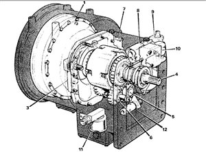
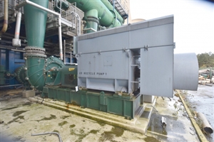
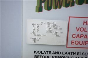
Firstly: what checks can I best do for a possible purchase of a single ABB - AMB 630 LC16 ABA C 530kW pump unit, which is unable to be properly tested (powered up) as the plant it was operating in has been decommissioned, and is currently being scrapped.


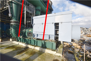
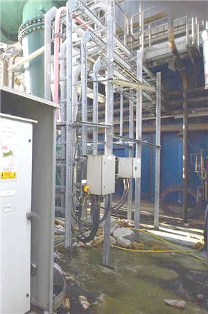
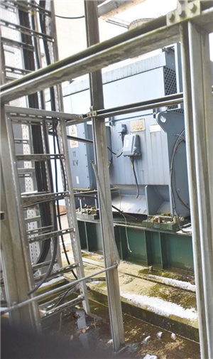
The unit appears to be mostly self contained, with a separate 'powercap' capacitor cabinet.

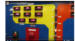
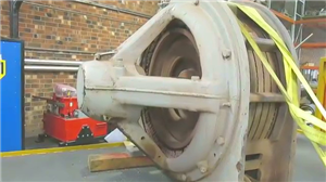
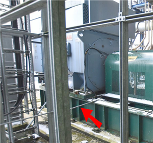
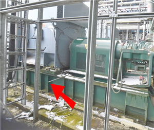
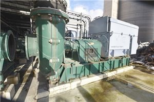
There are 8 in total, in various conditions and all look like this:
200fe3153df9ce950ab8d3220e14538c-huge-1.jpg
b9f52bfa5dd0afd26e92e2d1d4f97d2c-huge-2.jpg
9b08e6def31b626893d8d9e9b05b139f-huge-3.jpg
acf1cd9e473f756f328529e5cb2fc6d0-huge-4.jpg


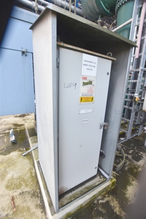
Secondly: No switching gear is 'included', however I could always ask the company (who's pulling the site apart) if it's possible to obtain the original starter systems maybe???

But would this be a good idea, considering again it's in an unknown condition.


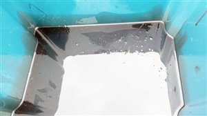
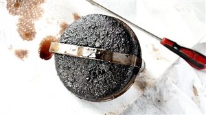
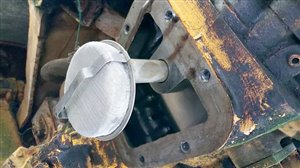
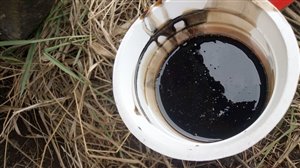
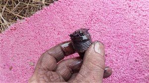
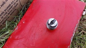
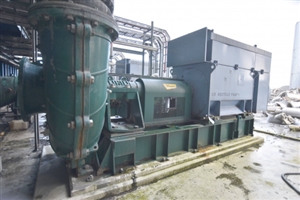
From the 8 available, I've selected 2 that appear to be the most suitable for hopefully reusing again (not bashed about, leaking oil etc) and thus generally look ok, so possibly from that can choose the final one.... but it would be great to know how best to maybe pick the best from any testing that could be done where they stand now, without any power.


Obviously with big industrial machine as this, it's not your average consumer second-hand electrical goods....

....that one just plugs in, and then hopes it works when power is applied!


(Thanks in advance to any replies)
  • Former Community Member
    0 Former Community Member
    These big motors really do sound like a jet aircraft in operation!


    Here's another testing video just found

    It's odd as I thought most induction types had to be 'load' tested only, because running it unloaded ...was a nono?


    When at Tech college we did large 3 phase motor starting, and it had a huge friction belt setup because the lecturer said that without loading the motor could easily overheat due to high starting winding current, and even over-speed and then could possibly fly apart.


    I remember this weird but huge 'Frankenstein panel' where you had to get the phases inline and then after doing something else that I can't now recall ...pull over a huge switch that then set the motor into a running state from an initial starting mode?

    ...or something like that


    Anyway sadly can't go back and check because I did try to revisit the college about 5+ years or so ago (for old times sake as it was such a wonderful place that taught me so much over 4 years), but on exiting the main building to go into the next, the ENTIRE technical block (the machine shop, vehicle repair and entire indeed the whole electrical + engineering section) had been...

    demolished


    Nothing there anymore!

    I could not believe it


    Anyway, I'm thinking now motor testing is possibly best done by a specialist, certainly as the 11kv power requirements are not exactly easy to get hold of, and it's very likely the National Grid won't even allow an untested motor to be just 'connected up' anyway.

    If there are any UK based specialist motor testers who see or find this thread please get in touch and post a reply if you can take in a large motor for proper testing!

    I could check the pump out ok, but now don't really think motor testing is possibly something I really should even attempt myself, and it would be far better to send any pumpmotors I can obtain off to be properly tested.


    It may also upset the motor if the pump was actually disconnected creating a no load while trying to prevent the dry running of the impeller and/or seals?

    Not really sure.


    Just trying a motor and hoping for the best it seems can have major drawbacks......!

  • Former Community Member
    0 Former Community Member
    Ummmm ?


    I've been simmering these last few hours of Sunday night thinking about these motor tests and stuff.

    I could never understand politics, and how they usually ALWAYS seem to make a total hash of everything?!


    Cannot allow a coal fired power station to operate, because it's environmentally unfriendly.

    So, someone, somewhere, signs the order to then close it.

    Ah, and now they're now green!


    Actually no, never thought to think that MAYBE some of that equipment inside could actually be reused?

    Oh dear.

    That's rather an oversight, and not so environmentally friendly.


    It's the demolition company to their great credit now that's trying to find a reuse for varied things.

    Well done to them.


    They are the more environmentally thoughtful, than the people who decided to close the site!


    But, it's not so easy now, as what works, and what doesn't - plus, how can one even test anything??

    If someone had the foresight to just think, it would have been so much easier.

    All reusable equipment could have been checked while still in operation, then given a test certificate thus making it much easier for anyone (like myself) wanting to try and reuse it, after the site was closed.

    Safer too.


    But of course in the real world, sadly that doesn't seem to happen.


    Oh, but now one can have a 'right to repair'!

    Ok, but consumers have been complaining for YEARS that when their fridge, cooker, TV etc conked out, they found it impossible sometimes to get it fixed or the manufacturer would not supply spare parts and "Buy a new one" was the usual response.


    Interesting, the sudden change now of thinking.

    Shame the landfills are clogged up with lots of broken appliances that could have been fixed years ago.


    Maybe these people in politics do actually live in a bubble, and never see the real world .....until it's rather too late.

    Perhaps this is also why so much good stuff got scrapped and still seems to, as certain people can't be bothered to do anything else with the 'waste'?


    Oh it's now Monday.

    This week, possibly things may improve?!!!!


    Watching the repair of that lift motor was really an inspiration.

    I've always tried to repair many things.

    In Russia, they obviously always mend it too, and make do again.


    Here, (possibly) someone would have just said......Oh,

    sorry, you need a new motor!

    (...there are no spares available for that old one now)
  • That TigerTek motor test video was fun. As is their multi-level starter. very sensibly it looks as if they do all the switching  at LV - hence the 208 phase to phase rising to 585 phase to phase as the max setting. The HV side (1k8 phase to phase rising to presumably 6k6 but the top HV label is missing) is presumably a fixed ratio transformer.

    To start an unloaded motor at 1/3 of the volts in this way is a sensible precautionary approach. But the ratchet straps do look a bit weak. I also remember being told by Rolls Royce engineers never to stand to the side of any engine under test, nor directly behind it, as mostly things either come out at a tangents sideways, or straight out the back.

    If it does fail the safest place to be is not in the building, but failing that, some way off, at at about 45 degrees to the axis.


    04b9c563f1bf96b2efcc3fc385d58657-original-motor_test_panel.png


  • Former Community Member
    0 Former Community Member
    The motor testing on site is probably limited to continuity, winding resistance and ideally a 5kV insulation resistance test.

    However and I apologise if you are familiar with HV working, do not yourself or have anyone working for you access the HV terminals unless you can either see the cables to the motor cut off or the demolition firms authorised person provides a permit in writing. To work on an HV circuit it should first be isolated & earthed and then for your testing the earth removed. Hopefully if the plant was properly shut down ??? the motors will have all been isolated and earthed at the switchboard. I would have expected each motor to have had probablky a vacuum contactor / HV fuse  with an isiolating/earthing arrangement for each motor. The panel then probably fed from a 11kV breaker at one of the power station's substations.

    Some one competent to work on 230/400V low voltage systems would not necessarily be deemed competent to work on HV.

    When doing any tests check out any auxiliary circuits if there are any (i.e. anti-condensation heaters or winding/bearing temperature sensors).

    On a side note in the video a rubber mallet wouldn't cut it to get the end plate off the bearing since it should have a small fit to prevent any chance of ther bearing rotating in the the end plate. Your size of motor will I have a bearing housing which bolts to the end plate and bigger units can have split bearings. Originally there will ahve been clamps to secure the shaft for transport but I doubt you will find them, However as said before protecting the bearings during transport is important (in all 3 planes) other wise the ball/rollers and the races will get damaged. My guess bearing arrangement is ball at NDE and roller at DE. The ball bearing providing the axial location for the motor.

    Not knowing the details of where you want to use the unit, does it have a strong enough supply to support starting this motor? At the power station since supplies will have been probably quite stiff it may have just been DOL or at best Star/Delts unless they used reduced volts etc. to soften the water circuit effects. Just saying make sure your location and local DNO would be OK with this size of motor and possible what kind of starting you will need to consider.


    Hope this helps, good luck.

    Ian
  • Former Community Member
    0 Former Community Member
    The TigerTek motor test indeed was very impressive.

    Certainly a great bit of kit they had!


    Interesting though that on 120v each phase is drawing almost roughly the same current A57, B50, C49.
    3499cbc36a94497c930923319faa867e-original-vlcsnap-2021-03-17-21h22m12s515.png

    Stepping up to 208v it's A76, B65, C61 so again virtually the same on each phase....
    5a5ce03b265805d69db05465b4af4be5-original-vlcsnap-2021-03-17-21h22m33s046.png

    At 240v however it then begins to alter ?? A86, B74, C68
    5db9b27f67a2f532b1154e2cafb51f52-original-vlcsnap-2021-03-17-21h23m05s156.png

    At 380v it's..... A134, B121, C103
    8d594124425c80be94957511dd765c03-original-vlcsnap-2021-03-17-21h23m21s062.png

    At 480v, A172, B166, and C141
    a7ab6592e796eb6af7ae3f193aa04e51-original-vlcsnap-2021-03-17-21h23m40s093.png

    All voltages are almost the same, BUT phase C's current draw seems way lower compared to A.

    Does anyone possibly know why A was pulling far more current, than C?

    Is that normal??

    It seemed odd to me, A taking mostly the highest load current.

    That would mean A is loading far more than the others which could result in a premature failure.

    I thought the whole point of 3 phase was that each phase loaded equally, which thus providing a balanced power loading?

    ?


    Also, yes - if there had been a catastrophic failure of a bearing, or a fanblade breakage...

    Certainly that high inertia in the rotor, would not have been held by those straps!
    8701ce258c51d42be93ccb23b2458a43-original-vlcsnap-2021-03-17-21h24m43s203.png

    I don't know how much that motor weighed, but having that stall and then fly across any workshop wouldn't be a good outcome ?


    ABB have been superb, and sent over a superb PDF motor manual which gives tons of info, here are a few screenshots of stator and rotor winding checks, and also brush pressure.
    f44a2d575afefede9099520e16a5ed4f-original-stator_winding_resistance_checks.png
    54dbe7e49910df27179cd8a8532f9a1c-original-rotor_winding_resistance_checks.png
    e8f4f6b2fc4956c34027ed8a25f4a329-original-brush_pressure.png


    It does also mention anti-condensation heaters and temperature sensors too.


    Additionally it mentions oil leakage and the possible causes!

    bcc37a479e8f8a4f28a107158bc779f1-original-oil_leakage.png

    Certainly a superb manual.

    Warman have also been super, and sent a PDF of their pump ?


    I have no idea as to how the motors were disconnected, if the power station engineer did that or it was done by the demolition company.

    Worryingly, lot 9 shows a small conduit feed intact:
    65f04d0b5dd5a961839430c1c4afd116-original-lot09.png

    Possibly a sensor line or some low voltage feed, anti-condensation or temp control maybe.


    However lot 10's conduit has been sheared off......
    04cabf66381242d1bcbfd852dbc083bc-original-lot10.png

    The motor's frame bolts have also been undone.


    Look closely again at these two pictures.... and both shows other cable lines cut.


    It would appear that (maybe) most have been 'pruned' with no regard for the reinstallation of the machine.

    If it was a feed into the actual plant then sobeit, but if just to a nearby controller box or sub-unit then the entire cable (or cables) will all have to be replaced (at extra cost), when they could have been simply disconnected carefully from one side and easily reconnected again at the new site.


    Could also be a major problem if associated equipment and/or panels/boxes are removed or even lost.

    It may not be possible to easily reinstall things properly!


    Looking rather a mess... and it seems reading the manual the cooler unit (topbox) was delivered separately on any initial motor installation, so possibly that should come off before the motor is even lifted out.


    The entire motor (as it sits on the concrete pad) wasn't designed to be craned out in one go.

    Hopefully someone doesn't attempt this, or the base frame could get badly bent.....

    Worse... one of the eyebolts breaks from an overload

    OR the cooler is pulled apart from the motor, and the motor then drops to the ground.


    The new site location for any motor purchased would yes have to have a suitable supply, but I was trying to get a motor, (or motors) just saved from any damage really.

    Getting them out certainly from the demolition area..... before being wrecked beyond any use.


    I do though wonder, if they haven't already been, or will be??

    Doesn't look good.
  • Former Community Member
    0 Former Community Member
    Can't sleep so having restudied further the photo of the green main frame, I think even IF the unit could be lifted directly straight upwards (which doesn't seem possible due to the overhead pipework), it will end up tilting backwards and then drop down onto the rear end, possibly wrecking the topbox cooling unit.
    2499d943e5bc37682eb8a76aac71f0cf-original-lifting.png


    It appears to me that the motor was put on last, so for removal the topbox cooler indeed has to come off first, then the main frame could be balanced properly .....but maybe the motor still has to also come off, and only then can the main frame be lifted?


    If the motor transport locking devices must be active BEFORE moving the motor, they can only be accessed really once the topbox cooler is removed anyway.
    7217dce9fac574b1ae721e62898bfc34-original-transport_lock1.png
    895e5ea277ba41fa02505542e8e12376-original-transport_lock2.png
    5a1e0cf3b57c60dc061a51d94df86020-original-transport_lock3.png


    To me, it doesn't look like the unit can be lifted up (as it is) in one piece, but judging from and looking at the photos.... with cut cables, it appears (maybe) to be exactly what someone is trying to do?

    What does everyone else think?


    The rear lifting eye point is NOT at the far end of the actual green main frame - which surely with the cooler unit thus makes it heavy in the 'ass'!

    Is it likely to tip back, or actually remain level?


    While the pump is quite a heavy unit, that big motor I'm sure weighs far more to cause a rearend imbalance drop....
    50ec049aba13a61c6dd92a13a2712840-original-sideview.png

    Were the liftpoints on the green frame actually designed to lift the ENTIRE unit as it is, or simply to align the frame properly onto the concrete foundation bolts.


    I somehow think the frame was put in first.

    Then the pump fitted on.

    Then the motor.

    And finally the cooling topbox.


    Any thoughts?


    While you are thinking about that....


    Having looked closely at the photos, the 11kv line appears NOT to come in via the red tubing conduit (as I'd previously thought!) red as a good warning for HT lines.


    The 11kv seems to be routed loose along the cable channel frame, into a cabinet to the right of the capacitor cabinet?
    33f220b511dd4485133cba520eca6320-original-wiring.png

    Certainly an emergency stop switch there, with a further smaller cabinet to the side.


    Strange.


    In another photo the motors 11kv terminal box can be seen but no thick 11kv wires anywhere.....?
    05a4cb66f454c4cf703e5c3734f971a2-original-wiring2.png

    But again, many cut or sheared through smaller cables.

    Two terminal box cables on the motor also cut through.

    Yet more undone frame bolts!


    I'm certain now, someone is getting ready to then lift out the entire unit as a whole.........

    Not good?
  • Those lifting eyes will have a lot of margin in terms of ultimate failure loading, but I agree lifting it as an unbalanced load is not at all wise, really it needs to be done in the way that removal is the reverse of assembly. And that is before worrying about transport locks and so on.


    The 11kV lines wont be that thick - you are only looking at about 20A or so  per phase, so more insulation than copper - the copper core could be a few mm2, with half an inch of insulation - that is the joy of HV.

    Glad you got good intel from the makers, pity the dismantlers do not have this rigour of approach.


    Yes I noticed the variation in current on the tigertek rig - I presume that is why the motor is there to be fixed, it may mean there is a winding or an alignment fault, or the calibration on the rig is  bit off, or less sinsister, perhaps there are unequal resitances in the hook-up wiring. (though the secondary currents will be pro-rata less, the odd ohm astray could be problematic.)

    M.
  • Former Community Member
    0 Former Community Member
    ?

    Sadly I'm possibly done with these motorpumps via the auction process (which ends on 31 March), as not only have they stated everything must be cleared without fail by 4pm Friday 9 April (so, excluding the weekend, that's only 7 days!) but now a sole principal contractor is appointed to remove ALL of the fixed plant & equipment.


    Any purchaser MUST now use this sole principal contractor.

    (The contractor will produce a priced list for the removal of and loading onto purchaser’s transport available prior to the auction sale).


    I very much doubt they will properly disassemble everything anyway (even now it didn't look good) and if they offered to do it 'properly' the price charged would bound to be excessive, far more than it would take me any maybe 2 others to do.

    Yes it will take a time to disassemble but I'm certainly not risking an unknown contractor doing it, and maybe also trying to lift up the entire mainframe with everything on it.


    Had thought someone was certainly attempting an entire lift/removal process with these motorpumps, but that simply cannot be done.

    No bearing locks fitted, and so who knows what condition the unit(s) would be in on collection.


    Unacceptable terms!

    A huge financial risk too, so my final hope today was a direct email to the demolition company asking if it's possible to do something directly with any unsold units, BUT removal has to be done properly if there's any hope of these units ever running again.


    Basically if that fails, then it looks as though all of these wonderful motorpumps could indeed be heading for scrap but I'm not prepared to spend 9k+ saving them AND transportation costs...... to haul away what in reality could be junk.


    However, all is not lost, waiting may be the best option as the West Burton power station is possibly due to close soon and thus it might be possible to arrange a purchase of their pumps (and hopefully also actually see them working!) before that plant is closed down.


    Everything could then be properly removed in a safe and ideal manner before that plant is begun to be demolished.

    Anyway, back to the auction and there are some good items in the stores that hopefully can be won and then be reused, but I'll only watch to see happens now with the 8 motorpumps, and no bids.
  • Former Community Member
    0 Former Community Member
    As any engineer knows...


    Things are worth doing properly, or not at all!


    This is off topic from the motors but I would like just to take a while if I may to say many thanks to a JCB service engineer when I asked him about how best to move an old machine that hadn't run for 7+ years.

    He determined it was a later type and was fitted with a torque converter (no clutch) so DO NOT attempt to start the engine!


    Why (I said) as everyone usually just did exactly that!

    Because (he said) the TC is directly connected to the engine and there's thus no way to stop it turning over when the engine is from the starter.
    ff02fc1c98056db1c8e4bf830b7812d6-original-torque_converter.jpg

    Basically it's a vital part of the machine, and was designed to allow a fast forward or reverse shuttle (thus avoiding clutch wear) with a gearbox behind it then allowing for selectable drive speeds.


    IF the machine has sat for years then the sump is bound to be full of gunky oil (very unlikely it was ever replaced!) and worse, the ONLY filter is the sump screen, which is also likely to be blocked.


    Try to turn over the engine and either the old gunky oil will then be sucked into the torque system (with all the usual detritus too).... worse, no oil will get through and the unit will be totally starved of oil, or the main hydraulic gear pump can even 'pull in' a blocked strainer, rip it apart and open, then drag all of that first into the pump, and then the TC system too.

    DON'T START IT

    Drain out the old oil, clean the strainer, refill and then you should be fine!

    It's also possible to have just totally saved the entire transmission system from damage!

    Because series 5 machines are becoming rare now, as most have been wrecked by no real care and attention.


    As he knew these machines well, I took the advice and didn't attempt a startup.

    (Despite others saying 'oh just do it')


    Towing away wasn't an option as it had no brakes with a 7ton machine weight, and even the local HGV recovery service after doing a risk assessment refused to move it.


    So, with no other option I did as he'd said....and first drained the TC's transmission oil
    9eb9d6dc98fcc880913edb223d2ca5f6-original-transmission_oil.jpg

    Certainly awful - and not the lovely cherry red that Dexron should be!


    Next the sump removal and to check that strainer...
    32d88a8bbab86261aabbae6fdba5e5b8-original-blocked_screen.jpg

    TOTALLY clogged up, just as he said!


    After a good clean, this is what it should look like
    2feadae3aa394f8a7f0da46ff6069d13-original-clear_screen.jpg

    Wow, just a few minutes work being careful, and that DID likely save the entire transmission system!

    ?


    Better change the gearbox oil too, as he also suggested.

    Here's a sample of that.....
    86ba720c5980d6ba81815f8717be1ff3-original-sumpoil_gbox.jpg

    Not good!

    AND check the sump plug, he advised
    6c811fc5260857eabd210780b6b8f4c4-original-gearbox_sump_plug1.jpg

    Loads of ex-gear metal filings stuck onto the magnet.

    But easy to sort that out
    72c679ce1f9bf9fdebc6baeb9ffb345d-original-gearbox_sump_plug2.jpg

    and now it's ready to pick up any other loose bits!


    The transmission gears often get rather trashed (he said) as people usually forget to return the shuttle lever to mid position (neutral), BEFORE changing gear!

    He was right again.

    So MANY thanks.


    This actually returns to those pumpmotors and how very important it is....

    doing things properly!