This discussion is locked.
You cannot post a reply to this discussion. If you have a question start a new discussion

13A 1362 fuses and flex

Good evening everybody. 

I've been cogitating on the fusing factor of 1362 fuses (specifically 13A fuses)  and how this correlates with the protection of a 1.5mm2 flexible cable. As ever I am hoping you can shine a light!

The code of practice for the in service inspection and testing of equipment  Table 15.6 states that for flexes to be protected by the fuse in a BS1363 plug there is no limit to their length providing that their csa's are as in table 15.6 which states a minimum flex size of 1.25mm when using a 13A fuse. I am minded that it is quite common site to see a multi-gang extension lead on sale using 1.5mm2 flex where there is obviously potential for overload given the unknown nature of what would be plugged into them (even though there will be a warning not to intentionally do so).

From the Beama guide:

2.5 The BS1362 Fuse
The UK uses a fused plug which must be fitted with a BS 1362 fuse. For domestic
installations the use of the BS 1363 plug and socket system and the fitting of a BS 1362 fuse
into a plug is a legal requirement under the UK Plug and Socket Safety Regulations, 1995.
With a correctly fused BS 1363 plug, the flexible cable connected to equipment is always fully
protected against the effects of overload or small overcurrents as follows:
3A fuse protects 0.5mm² cords
5A (6A) fuse protects 0.75mm² cords
13A fuse protects 1.25mm2 cords
Protection against excessive damage by a short circuit is still achieved even if the smaller
cord sizes are inadvertently protected by a 13A fuse. In addition, it has been accepted in the
UK that some marginal damage to small flexible cords is tolerable under short circuit
conditions, for example where a 0.22mm² cord is used with a 13A BS 1362 fuse.

As far as I understand it the fusing factor of a 1362 fuse BS 1362 fuse is 1.9 (0.763) although in fairness I have seen lower fusing factors quoted (1.66?? which removes the particular problem I am wrestling with.)

Reference 4F3A a 1.5mm2 single phase AC flexible cable has a tabulated current carrying capacity of 16amps. 16x0.763 = 12.208 amps which is obviously less than the 13 amp rating of the fuse. 

I find it quite common to see 13A 1362 fuses inline on 32A cooker circuits protecting 1.5mm2 flexes to ovens. Is this deemed acceptable even though the oven isn't strictly speaking a fixed load (fan motor etc.)?

Is there another factor at play here which I am missing? Or do I just have the wrong fusing factor!

Thanks for your help in advance.

  • Well a 13 A fuse will carry 13A all day, and may not blow in any sensible time even at 20-25A, depending on manufacturing tolerances and environmental temperatures.


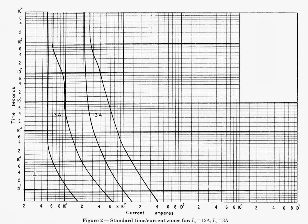
    Look at these curves and look at the ‘all blow’ right hand curve, vs the left hand ‘never blow’ limit for 13 and 3A fuses. 

    Now cable ratings are also a function of manufacturing variations, and most importantly cooling.  An extension lead knotted in a bundle or wrapped in pillows will overheat quickly even at the nominal rating, while a cable  in even a modest breeze will be fine at considerably more than the nominal ‘free air’  rating.

    Now the ratings tend to assume that the cable fails the moment the copper cores reach 70C but anyone who has dropped an off cut of cable into their coffee will know it does not melt immediately nor spontaneously combust. so the cable can be over run quite a lot before they actually fail. (power is proportional to current squared so if we neglect convection air movement increasing as things get hot, we might expect double the temperature rise from ambient from root 2 ~ 1.4 times the load current. so if for example 16A gets us from 30 degrees to 70, then 24 A may get us from 30 degrees to 110 degrees - still not cable failure but not good for you if you touch it..)

    But would you really want a cable at even  90 degrees in  a place you could touch it ?

    probably not..

    Mike.

  • I feel that the problem you are experiencing is more fundamental than you realise. Just what is an “overload”? You should also consider the question “why does it matter”, and consider the effects of an “overload”. I will leave this for a bit before offering an answer, you should write down a few notes as although this is not an exam question, it is often taught very badly indeed. Mike above has made a few of the points to consider, I will examine the whole subject to try to inject some deeper understanding. Beware, this may change your life! Back later.

  • Realistically, a BS1362 fuse will protect the flex in the event of a short circuit in the appliance.  The fuse will blow before the cable melts.

    But it won't prevent long-term overloads.  A single appliance (including an oven) should never overload the flex if the manufacturer designed it right.  But a BS1362 fuse will not prevent long-term overloads on multi-way extension leads.

    It's no worse than in other countries in that respect.  In the USA, power circuits may have a 20A breaker.  But the individual plugs are only rated 15A for short-term loads.  And they have no fuses in the plugs at all.

  • Thanks all for responses and apologies for my tardy reply…. Bit hectic out there at the moment!

    Simon's response correlates with what my understanding is telling me - which seems at odds with the pretty confident guidance/statements in the Beama guide.

    In the spirit of learning from my betters I will lay myself open to ridicule! I'm faintly terrified at having my life changed though! ?


    So what is an overcurrent and what are we concerned about?

    131.4 Persons and livestock shall be protected against injury, and property shall be protected against damage due to excessive temperatures or electromechanical stresses caused by overcurrents likely to arise in live conductors.

    Note. Protection can be achieved by limiting the overcurrent to a safe value and/or duration.

    Part 2: Overcurrent: A current exceeding the rated value. For conductors the rated value is the current carrying capacity.

    We're concerned thermal effects of the cable overheating possibly causing fires or injury.

    433.1.1 The operating characteristics of a device protecting a conductor against overload shall satisfy the following conditions:

    1- The rated current or current setting of the protective device (In) is not less than the design current of the circuit and

    2- The rated current or current setting of the protective device (In) does not exceed the lowest of the current carrying (Iz) of any of the conductors of the circuit, and

    3- Where I'm getting turned around. The current (I2) causing effective operation of the protective device does not exceed 1.45 times the lowest of the current carrying capacities (Iz) of the conductors of the circuit.

    Leading on to… 433.20/202 where an allowance is made for the fusing factor of a 3036 fuse. If the fusing factor of a 1362 is at 1.9 it is fairly comparable so surely we must apply a comparable derating factor?  This is where the wheels come off my bus if the answer is more than just… It doesnt protect against overload.

    I appreciate that there will be manufacturers tolerances both for the device and the cable (which could go both ways) and that there is undoubtedly going to be some headroom in the cable. I've seen a plumber leave a 9.0kW electric boiler on a bit of 1.5 flex before and yeah (prior to me fixing it) it was pretty hot after a few hours but it hadn't melted! Is the answer just that we're only talking about an extra amp in the example and whilst it may get a bit hotter than would be ideal this isn't the end of the world or are we into the realms of trying to work out how much heat is being dissipated during the fault by the flex as it is going to be happening over quite a prolonged timeframe?

    I'm braced. Be gentle and again - thanks for your time.


  • Well, it is a bit like peeping behind the curtain at the Wizard of Oz, to realise that the whole edifice of current ratings and so on is not perhaps as precise as the significant figures in the appendix suggest.  

    Belief in the numbers is for those who like a simple life. Life is not simple, as above,  13A fuses do not blow at 14A, and 27 amp cables may already overheat at 25 or be fine at 35, in very similar looking arrangements, and in many ways it is “measure with micrometer, mark in chalk and cut with axe” in that the apparent accuracy is a bit of a myth - well, if you re-create the exact  test conditions you will probably re-produce the readings, more or less, but cables, especially flex, are never installed exactly like the test rig really. Given that convection is gravity dependant, you may ask why readings are not separated in to vertical and horizontal, with a few amps between them, or why the rating is not less near the ceiling. Luckily, there is usually a fair amount of slack in real systems relative to the book value, and most over loads are not on long enough to matter. (The warm up time is also very variable - the substation at the end of your street may be loaded to 200% for an hour a day without suffering any immediate issues,  cables in plaster warm  up over tens of minutes, and wires in free air are very affected by drafts, and the air in a house is almost never totally still) 

    There is a reason that double sockets on a 25mm spur from a 32A ring seldom suffer from cable failure.

    Mike


  • Right, my turn again.

    You have read in BS7671 and heard from your tutors that cable ratings and fuses or breakers are absolute, but they forgot (as BS7671 does too, probably to its shame) that all the “magic numbers” are for 24/7 continuous use. They do not take any account of short-term loads and suggest derating factors based on ambient temperatures of 30 degrees. Whilst this may be reasonable for a large industrial plant, it very rarely applies in domestic properties, and if it did you would not be able to afford it anyway!

    Looking at our twin socket as Mike did above, how many people would plug in 2 13A consumption appliances for 24/7? Realistically they might for a short period say 30 minutes to heat a cold room, but as the ambient is then well below 30 degrees the 2.5 mm cable would not get more than somewhat warm, and certainly not melt or catch fire! In fact, I will point out that almost all of you will NEVER have seen a domestic cable that is rather hot to touch, probably only at 50C. Fire cannot occur unless temperatures get to at least 250C, the temperature of a hot oven. Even if you leave the bread in here it will only char, but not burst into flames unless you put too much oil into the mix!

    Danger of damage comes very specifically, and this is a long relatively small overload, not for the odd hour, but weeks at a time. This time allows the cable to reach thermal equilibrium with the environment but is insufficient to open the CPD (fuse or breaker) because of its fusing factor. Breakers have lower “fusing factors” than fuses, so,in fact, provide more protection from this situation than fuses.

    All of this means that discussions (which we often have here) on the effects of overload are generally misplaced, and lead to erroneous conclusions. A 13A socket strip loaded to 20A will probably pop the plug fuse at some stage, not immediately but perhaps half an hour as the fuse local environment gets hot due to the fuse resistance, and poor ventilation inside the plug, but it will take much longer than this to raise a 1.5mm cable above the 70 degrees rating of the cable, and even if it gets to 80 degrees will not cause any great problem as PVC melts at around 140 degrees C. Even if melted it still cannot start a fire in solid materials, although if you drop cellulose thinner on it a fire might result! This would clearly be unwise. Actual melting is very likely to lead to a short circuit and immediate disconnection.

    The outcome of all this is to not worry about these minor domestic overload problems, as one can see from the normal use one sees, they rarely cause any trouble at all. Loose connections are the cause of problems, not overload of cables. 

    Your life should now be changed for the better because not understanding this subject is often the cause of worry. It is not well understood by the average electrician, or most college tutors I have met. If you want to look further you may get into the complex study of thermodynamics and more physics, but at least you should now see that there is much more to “overload” and that the TIME characteristic is very important indeed.

  • If I have my decimal point in the wrong place, please forgive me.

    Take 1 m of 2.5 sqmm T&E and pass 20 A in a vacuum - so no heat losses.


    Live conductors 2.5 x 1000 cumm = 2.5 cc

    1 cc water weighs 1 g

    Relative density of copper = 8.93

    Mass of copper in one live conductor = 2.5 x 8.93 = 22 g

    Total mass of copper = ((2.5+2.5+1.5) / 2.5) x 22 = 58 g

    Mass of cable = 120 g/m (Eland Cables)

    Mass of PVC = 62 g


    Specific heat capacity of copper = 0.380 J/g/K

    Heat up cable from 20 - 70 deg => 1103 J


    Power loss in one live conductor = I2R = 20 x 20 x 7.41/1000 (OSG) = 2.96 W

    Power loss in both conductors = 5.93 W

    1 W = 1 J/s

    Time taken to heat conductors = 1103/5.93 = 186 s = 3 minutes


    Specific heat capacity of PVC = 0.9 J/g/K i.e. about 2.5 times copper

    Time taken to heat whole cable = 10 minutes


    Assume steady state at 70 deg C RM A (Table 4D5) so heat loss = 5.93 W

    At the beginning, 100% of the heat generated in the live conductors is available to heat the cable. At 21 deg C, only 98% of the heat is available because the loss is 1/50 of the amount at the steady state. At 22 deg C, only 96% is available and so on. So looking at 1 deg C increments, it takes in fact 45 min to get to 69 deg C and you never quite get to 70 deg C. Please forgive me for having forgotten the calculus which I learned 45 years ago.

    So there we are, a 2.5 sqmm cable loaded at 20 A will take over 45 minutes to get up to 70 deg C from 20 deg C enclosed in conduit in an insulated wall. Any smaller loading or less lagging and it will never get there because the heat generated in the conductors will always be less than the available heat loss.

    That's my back-of-a-fag packet take on the situation.

  • I assume your vacuum vessel is mirror lined so no radiation loss ?.

    Then I agree with the several mins figure for a 40 degree rise. The conductor only version is the basis of our old friend the adiabatic calculation, where it is so fast that the heat does not have time to stabilise to  a uniform temp throughout the PVC, so we pretend that no heat is lost to the insulation at all, as the temperature rise calculated that way is always a safe over estimate, so we safely under estimate the let-through energy the cable can stand.

    In reality only AWE or CERN will install a cable in vacuum like that, and of course any real cable will heat quite a lot more slowly.

    The heat up rates for the different mounting methods are variations on the problem of filling a leaky bath, with the complication that the rate of leak varies with the depth of water. Some things, like heating a 4 inch thick brick wall on one  side of the cable, have very long time constants, and others, like a cable sandwiched in between layers of something like Kingspan insulation are much closer to the ‘vacuum’ case, as the stuff has almost no heat capacity.

    Mike


  • mapj1: 
    I assume your vacuum vessel is mirror lined so no radiation loss ?.

    Then I agree with the several mins figure for a 40 degree rise.

    I just knew that one of you would mention radiation. ? But I am greatly reassured that my fag packet and pencil are not awry.

    It all goes to show that the 10 min shower, 10 min drying cycle can be repeated several times without worrying.

  • A real world example. 

    A few months ago I found myself with mapj1 junior in the car at a remote place with a defective battery. The jump leads were in Mrs mapj1s car at the time. Then it began to rain.  That sort of day.

    I was able to rustle up a short length of 2.5mm cable off the end of a reel, and the use of another car battery from an alarm engineer.

    Thought process ran like this..

    The car draws 250 to 300A to spin the starter.  How long can I crank the engine while my son and the nervous alarm man hold the 2.5mm onto the 2 batteries without burning either of them ?

    Now I did not quite use Chris's figure of 3 mins at 20 A, but if I had it would have scaled to 3mins/100 at 200A, or about 2 seconds for a 40 degree rise.  I had a more optimistic figure, allowing a bit for the PVC, and as I did not have the regs with me, so used a pidooma figure from memory.

    But I know the cable starts cold, I'm a bit more gung ho than the book ratings, as I do not care if the cable is ‘lifed’ afterwards  and so I can allow myself  a larger change in temp, perhaps 50 to 70C. 

    That “sum” suggested 

    “a-one and a-two and a-three.”  for cranking time, And relax and cool for 15 -20 seconds before retry  so average current is perhaps 20-30A.

    As it happened, the engine started midway through the  2nd attempt, and the cable was blood warm.

    When I described the thought process, the wide-eyed alarm installer said 

    “ I'd never have dared to do anything like that -  2.5mm is for 16 amps innit ?” well maybe under some condition, not sure what alarm chaps get taught about installation methods and de-rating..

    The only place that came slightly unstuck was one of the ends where the contact area to the battery was much less than the copper cross-section, and it spot welded. Well, sometimes wire cutters are a man's best friend, just keep the revs up a bit mapj1 junior while I find them.. 

    I now have a shiny new car battery without a tag of 2,5mm wire stuck to the terminal. 

    Mike.

    PS and the jump leads are back in the boot. all is well with the world.

    edited for a couple of nasty typos and readability.