High ZE compared to SSE figures on a TN-S

Hi, I'm carrying out a periodic EICR on a factory, can any inform me of the correct procedure for gaining a ze at  origin as I have always used the 2 wire method with main earth removed as stated in the on site guide, I have a reading of 0.77 ohms on a TN-S which is no where near the 0.22 ohms that SSE has recently recorded as they had to attend to the newly installed service head ( 5 years old ) due to some loose connections. The only way that I can get my readings that low is to use the 3 wire method.
  • What test current are you using ? older installations where things have become bit oxidised often need a reasonable blast to clear a path (by either welding it solid, so good connection, or blowing it clear so you can find the open circuit ) That said, reign that urge in if its a petrol station or similar risk.

    I'm intrigued by your 3 wire test comment - what meters are you using, and what is their quoted accuracy and tolerance ?  The results may be closer than you think.  I presume for 0.22 ohms its not a big service head - what are we talking 400A 3 phase or less  ?

    mike

  • Hi Mike,

    Many thanks for your response, the tester that I'm using is a Megger MFT 1741+ ( test current??? ), the tolerance for Loop ranges is 5% .The incoming supply is only 5 years old, TP&N with service fuses rated at 100A ( as written on the side of them ). My colleague who started this EICR obtained a reading of ze 0.77 ohms which he was a bit surprised for a high ze as the previous EICR was much lower, I verified the ze with my MFT, factory owner called out SSE who found loose connections in their equipment, they then obtained a ze of 0.22 ohms. I went back to site on Mon expecting a lower ze than what we originally recorded but it was more or less the same, results gained from bottom of the DNO isolator. The reason why I mentioned 3 wire method was it was the only way that I could obtain readings as low as 0.22 ohms, I only use 3 wire if there's a rcd downstream.

  • At least one of the meters is giving an erroneous reading. When was the calibration of yours last checked please?

    Which value seems more credible? For comparison, my Ze at home is around 0.23 Ω - 100 A TP PME supply. The nearest transformer is about 100 metres away, of which 90 are the street main. AFAIK, the transformers are in a network rather than a straight line, but that may give you a rough idea of what to expect.

  • Megger MFT 1741+ ( test current??? ),

    The test current for that model depends on the  particular setting you use for the loop test (changed by pressing the function key when the instrument is set to L-PE on the left dial, and Z or Zmax on the right one). The MFT1741+ 3-wire test also helps eliminate "RCD uplift" where if you are taking the measurement downstream of an RCD, the RCD coil can affect the reading. THe 2Lo and 3Lo settings are only intended to be used for measurements downstream of RCDs.

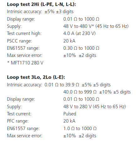
    If the setting is 2Hi, the test current is approximately 4 A, whereas if the setting is 2Lo or 3Lo, the test current is, I believe, a pulsed current of around 4.5 mA.

    It should also be noted that, if the actual loop impedance is below 1.0 Ω, the reading is unlikely to be too accurate on the 2Lo and 3Lo settings. Whilst the instrument has an intrinsic accuracy for lower readings for the 2Lo and 3Lo settings, the EN 61557 range is for those settings is stated in the manual as 1.0 Ω to 1000 Ω.

    So, perhaps worth checking whether the test was done on 2Hi ?

    The reading of any loop tester, particularly on low current setting, may be affected by current-using equipment operating within the installation, due to leakage currents and EMC ('noise').

    The only way that I can get my readings that low is to use the 3 wire method.

    The Megger 1741, 1741+ and 1845 have a "confidence meter" function, and the instrument takes repeated measurements to improve the "confidence" of the reading ... and so, what I suspect might be going on here, is that the instrument is taking "better" readings because of EMC "noise" on the 3-wire test.

    Or ... are you disconnecting the whole installation before testing with the 2Hi method?

    Megger's application note on the MFT1741/MFT1845 Confidence Meter appears to make it clear that the 2Hi setting should be used unless there is an RCD upstream of the point the measurement is taken ... so at the origin in a TN-S system, it would be very unusual to see a 2Lo or 3Lo test being carried out.

  • called out SSE who found loose connections in their equipment, they then obtained a ze of 0.22 ohms. I went back to site on Mon expecting a lower ze than what we originally recorded but it was more or less the same,

    Maybe the gremlins have come back and loosened it again? (or less charitably, it wasn't re-tightened properly, or the thread has been stripped so any attempted re-tightening produces only a temporary improvement at best, or there are several joints that weren't tightened up properly in the first place)

       - Andy.

  • My meter has recently been calibrated, both readings are accurate as they were tested in different ways, 2 wire between L/E, 3 wire between L/E/N. 

  • Or ... are you disconnecting the whole installation before testing with the 2Hi method?

    Hi, yes that's exactly what I did

  • I'm not  familiar with that tester but looking at the Meggar website 

    https://www.megger.com/sites/g/files/utfabz201/files/acquiadam_assets/2023-07/MFT1711-MFT1721-MFT1731-MFT1741_DS_en.pdf?changed=1739442054

    we see

    So on the hi  current 2 wire range, that reads 0.01 minimum, that could read between +/-0.03 ohms plus 5% of reading, so a reading of 0.77 could really be anything between 0.68 or 0.82, Had the other set of readings been within a few % of this band I'd have been muttering about 'identical within tolerances' but really this is not.

    Eliminate the obvious, dirty probes, poor contact between probe and circuit or probe leads and the meter itself etc, if you have not already one so.

    Is the supply really TN-s or TNC-s? given how new sounding it is, I'd expect it to be the latter in practice and if so there should be an N-E bond inside the company cut-out or near the meter but somewhere on the DNO side.

    If so, and there really is 0.7 or so  ohms in the neutral, I'd expect noticeable voltage drop issues - switching in a 30A load and dropping more than 20V will give very obvious lighting flicker and of course a low PSSC reading of 230/0.7 = ~ 350 amps L-E.

    I presume with 0.7 ohms, at that low PSSC,  there are issues about fuse clearing times for LE faults so it can't really be left.?

    Mike

  • Is the supply really TN-s or TNC-s? given how new sounding it is, I'd expect it to be the latter in practice and if so there should be an N-E bond inside the company cut-out or near the meter but on the DNO side.

    Or even somewhere out in the street. Where there are multiple supplies into the same building (or other situations where diverted neutral currents can become a problem) some DNOs now place once common N-PE link outside and run separate N and PE conductors from there to each cut-out. It might look for all the world like TN-S at the intake, but it's still very much PME and has all the usual dangers associated with that, other than a reduced risk of diverted neutral currents flowing between neighbour's metalwork.

        - Andy.

  • and of course a high PSSC reading of ~ 400 ohms L-E.

    I didn't quite follow that bit - did you mean 400 AMPS? (and low rather than high).

       - Andy.