Adding up current

In a ring final circuit
(Based on Paul Cooks commentary of the 17th edition)

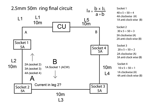
Very simple curent split using both legs of the ring

Not sure about adding up the currents in each leg
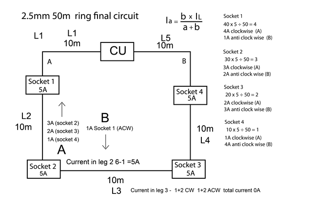
Take leg 2 Than will have the Ia of sockets 4,3 and 2
and the Ib of socket 1
How do these add up so you know the current in this leg?
Hope that makes sense
Thanks


  • You need to take the direction of the current (clockwise or anticlockwise) into account. E.g. 5A clockwise plus 3A anticlockwise on a given bit of cable gives a nett value of 2A clockwise. (Mathematicians would pick one direction as positive and so currents in the opporite direction are treated as -ve, so adding up works out).

    Taking a step back, the whole example is symmetric - same loading and same cable lengths - the left is an exact  mirror image of the right, so the currents must also be symmetric - anticlockwise current in L1 must be the same as the clockwise current in L5, likewise anticlockwise L2 must be the same clockwise L4 and so likewise clockwise L3 must be the same as anticlockwise L3 - i.e. L3 must be carrying zero current. If L3 carried any current it wouldn't be symmetric any more. Not true for the general case where loadings aren't so regular, but give you a way of sanity checking your calculations in this particular case.

       - Andy.

  • Thank you very much

    OK thats what I was curious about if the currents cancel out.
    So leg three would have 3A clockwise and 3A anti clock wise, so no current as you say.

    I see my initial sketch was incorrect
     Leg 2 would have 5 amps

    CW 1A, 2A, 3A  and ACW 1A  so a total of 5A

    I will put together a more realistic sketch

  • John, I think that it may help if you have different loads at each socket. Try 4, 6, 8, and 10 A. The resistance of the cables is much lower than the loads, so that may be ignored.*

    It may also help to turn on one socket at a time. So 4 A at socket 1 would be 2 A acw in leg 1 and 2 A cw in legs 2 to 5. Etc.

    *ETA: my apologies - that is incorrect.

  • Thanks will have a go at what you suggest as well

    Ive done this one, total currents seem to add up !

  • John, that looks good except that you have overloaded your ring with 41 A. :-) Leg 6 may run a bit warm unless it is clipped direct (Table 4D5).

  • The current share from each socket left or right is in proportion to the two resistance from that socket (lets call them clockwise and anti-clockwise paths) to the point of junction at the CU.

    There are two (low) resistances in parallel, between two places where the  voltages in the 2 wires are forced equal - both wires have to be at the same voltage at the socket because they meet at the terminals, and similarly the other ends of both wires are at the same voltage as each other (but slightly higher voltage than at the socket) once more at the CU,   

    So a socket half way round (in resistance terms, only half way in length if there are no changes of cable size.) sends half its load current either way.

    A socket at 9 O clock on the ring, sends 3/4 of its current on the short path, and 1/4 on the long. etc,.

    You can solve for the clock and anticlock -wise currents at each socket on its own first, then overlay and sum the answers for each segment.

    Mike.

  • Thanks for the help.
    The heating of the cable as mentioned above I guess is the prime consideration in a ring final circuit
    Especially as the sharing of the loads, cable lengths and installation methods play a large part in the 'total' overcurrent protection
    of the cable, especially as the protective device is rated higher than the cable


    Couple of questions if thats OK

    In the very first example where each leg was perfectly balanced. the currents add up to zero.
    This is a mathematical phenomenon of the net current?
    Im trying to visualise what actually happen say if a If a clamp meter was placed around the cable?
    It will measure a magnetic field (s) but there is a lot going on in a RFC with clockwise and anti clock wise currents
    and with AC direction change and unpredictable loads. Its hard for me to visualise...

    Ive done another example and tried to work out the heating effect in one section of cable.
    Am I doing this correctly (as in basic principles) Anything with heat i realise can get really complex

    Thanks very much


  • If a clamp meter was placed around the cable?

    If you clamp the whole cable (i.e. both L & N together) you'd likely read zero whatever current the cable was carrying - a the L & N currents should be equal but in opposite directions and so would cancel out the magnetic field the clamp meter reads (actually, if you did get a significant reading, it would suggest that L & N were not balanced - thus indicating a break or high resistance connection in one of the conductors around the ring).

    If you could clamp just one core (L or N) then yes, you should be able to verify your calculated  "nett" values.

    The bottom line physics is that to get a current to flow along a conductor (which will always have some resistance) you need to have a voltage difference between the ends of that conductor - higher voltage at one end and lower at the other and the current flows in one direction, reverse the voltage difference and the current reverses too. It's not possible for two currents to be flowing in different directions in the same conductor at the same instant. (The currents can flow in different directions at different times of course - which opens the door for a lot of cleverness when it comes to 3-phase work or combining different frequencies) but for d.c. and simple single phase a.c. using r.m.s. values, it can be treated quite simply).

    AT first glance, your power loss calculation looks right to me (I've not checked your actual numbers though). P=I²R is a re-arrangement of P=IV where V would be the voltage drop along the conductor - so it all stacks up.

       - Andy.

  • In the very first example where each leg was perfectly balanced. the currents add up to zero.
    This is a mathematical phenomenon of the net current?
    Im trying to visualise what actually happen say if a If a clamp meter was placed around the cable?
    It will measure a magnetic field (s) but there is a lot going on in a RFC with clockwise and anti clock wise currents
    and with AC direction change and unpredictable loads. Its hard for me to visualise...

    Think of water flowing down pipes. 

    In the first case, let's say 20 l/min flows through the stopcock (the CU). 10 l/min flows anticlockwise to tap 1. 5 l/min comes out of the tap, which leaves 5 l/min to come out of tap 2. Similarly 10 l/min clockwise to tap 4 where 5 l/min comes out leaving 5 l/min for tap 3. All the water has come out of the four taps, so there is nothing left to flow along leg 3.

    As for a clamp meter, I am afraid that the line and neutral will cancel each other out. You do have two conductors (or pipes) in each cable, but the flow is in opposite directions.

    To measure the current with a clamp meter, you would have to bring one of the conductors out of the sheath and clamp it on its own, but then you have destroyed your T&E.

  • Thanks for the replies.
    Yes I kind of understand an appreciate that we do not have currents crossing over each other in the one conductor.
    The current in any section is the result of all connected loads acting together,  and the current is what is is.
    With the ring sharing that current according to the resistance of the paths.


    re the clamp meter I understand the need to be on one conductor, as live and neutral should cancel out (Kirchhoff?) 
    unless there is some leakage.