good day folks
out of interest, if anyone has filled in the “rated time delay” entry on an EIC for a 61008 type-s RCD main switch, what was the value (presuming the standard has a set value/range) used and where from ?
regards
Habs
good day folks
out of interest, if anyone has filled in the “rated time delay” entry on an EIC for a 61008 type-s RCD main switch, what was the value (presuming the standard has a set value/range) used and where from ?
regards
Habs
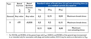
not quite the same question but at say 5 times the nominal trip current, 100ms is typical , and less than 50ms is a fail and 150msec is also. From here

If cascading earth fault relays I tend to use a rule of 3 for current and time as a starting point for modifications.
so instant 30msec fed from sub-mains supplied by perhaps 100A circuits with protection set to 100mA 0.1second, fed by generator of a few hundred amps, earth protection set to 300mA and 0.3 seconds. There are always exceptions, but it is a place to start from .
mike
@zoom that's the trip time range I believe (of which I was aware) ? The actual applied time delay is what I was referring to (see my comment about the figure provided by BG for their device).
I will have another check in Regs. but I think it might be one of those manufacturer things along side ensuring it all trips out within that specified time range.
The EIC seems to ask for the rated time delay (like one might set on an adjustable unit) … but that's not the same as tripping time range in my mind ( or is it ? ).
re: the table posted by @mapj -
is the ‘non-actuating’ value effectivel ythe max. allowed ‘delay’, so that for example, 130ms is the max delay that can be applied at Idn?
edit: to answer my own question, “no it isn't” as it appears to be the trip time range that is in BS7671.
I wonder if that box was intended for the likes of big boy's RCDs - earth leakage relays or add-on modules for MCCBs - that can have a definite (and likely constant) delay time.
S-types are just meant to be selective with instantaneous RCDs so often have a delay that varies with the residual current - so there is no one number you can sensibly write down.
I'd almost be tempted to write “S-type” and cross out the "ms".
- Andy.
@AJJ
I think that is favourite … where a time delay can be selected (adjusted).
Interesting that BG gave a figure when I asked though (see previously) and it wasnt current dependent (or at least they did not mention)… because perhaps of it's main purpose for simple selectivity.
5013601017570
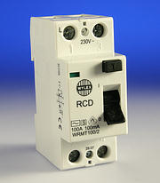
WRMT100/2

RCD terminal capacity,
35 mm
Wylex
100A 100mA Time Delayed RCD
2 Pole
100mA time delay
Suitable for use when total RCD protection is required to supplement
the system earthing and where local 30mA RCDs are used to give
additional protection against direct contact.
The time delay RCD will discriminate with the 30mA RCD.

Technical: |
Product Code
Description
| Price (ex VAT)
Quantity
|
|---|---|
WY WRMT100/2 100 Amp 100mA Time Delayed RCD 2 Pole - Wylex
| EACH
£42.60
Add |
Well, if the S type is slower in operation than 30mA instant types downstream, who cares about the actual trip time. As long as it is slower than say 40mS or longer?
Z.
was it worth posting all that @zoom , to then type “who cares about the actual trip time” . :-)
My question that I was caring about, was in relation to the space on the EIC for "rated time delay" and it seems reasonable to conclude that it is not really intended for s-types - so in that respect it's sorted.
We're about to take you to the IET registration website. Don't worry though, you'll be sent straight back to the community after completing the registration.
Continue to the IET registration site