This discussion is locked.
You cannot post a reply to this discussion. If you have a question start a new discussion

Temporary Connection of Generator to Domestic Distribution System

Hi All,

I recently came across a very interesting article - link below:

https://electrical.theiet.org/wiring-matters/years/2020/82-september-2020/mythbusters-6/

Where I find this article very interesting, is in relation to the requirement / or potentially non-requirement  of an Earth Spike, for the Temporary connection of a Generator to a building (in the article a Site Office is mentioned).

Please refer to the attached rough sketch / scheme for the Temporary Connection of Generator to Domestic Distribution System, which was originally based upon Figure 4 from the linked article - I wonder whether this could be considered, at least in principle, to be an appropriate proposal for the temporary connection of a generator to a domestic premises? In the attached scheme, there is no Earth Spike, and a 30mA RCD is included at the output of the generator, which would be connected to the generator via an appropriately sized SWA Cable. I would consider the potential for some nuisance tripping of the upstream 30mA RCD (in reality, this would be a rare occurrence) to be an acceptable price to pay, for the added protection that it would provide.

I would very much appreciate, if any of you could possibly find a moment or two, in order to share your thoughts in relation to the above / attached.

Thanks,

Harry G.
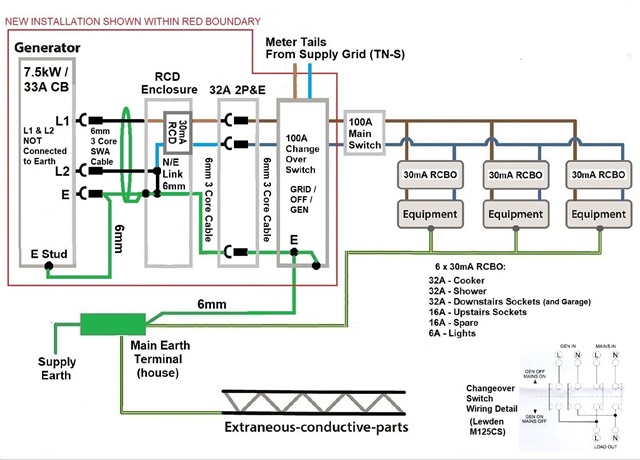

  • What  am trying to say is, it is difficult to see how any contact could be made between Gen L1 and Earth, other than via the Gen Frame, which is already bonded to Gen L2.

    I think it's more the fact that if you connect the generator with, say, an insulated and sheathed cable, rather than SWA or similar, the fault is more likely to occur in the connecting cable ... and if the cpc in that cable is broken, the generator is not Earthed, and what comes next is more difficult to ascertain.

    Where non-SWA cables are used, the use of RCD at the generator itself is imperative ... where a wiring system with metallic protection connected to the grame and neutral is used, risks are much less.

  • Hi Graham,

    Thanks for your informative answer. 

    I think that we will look at using armoured cable between the RCBO and the 32A Wall Mounted Plug - with the armour connected to the Earth Terminal in the RCBO Enclosure.

    There will be a short run of H07RN-F (appx. 1m) between the Gen 32A Socket and the RCBO Enclosure - the latter being a robust plastic enclosure, mounted on the generator frame.

    As regards the Earth Rod, I guess there will be no getting around this, as it seems to be called-for in the Regs, for Switched Alternative Power Sources?

    Best Regards,

    Mark G.

  • it has to be for any emergency genset that may run with the street main in a fault state - part of that fault may be that the cable is cut and there is no earth at all, so for ADS reasons you need bring your own.
    Mike.

  • I'm struggling with to get any where near 20 ohms for a suitable means of earthing as per 551.4.3.2.1
    I'm in the Lakes difficult terrain at the best of times.
    A previous generator fitted had no alternative method of earthing at all.
    If we're looking at an Ra value of below 200ohms on a TT system what exactly are the perils of not achieving a 20 ohm figure?
    The generator 1ph 20kVa is I believe delivered with 30mA RCD as well as overload protection.

  • 20 ohms is a figure that derives from guidance for to substations and similar, and has no immediate physical significance. Of course in that case there is of course no RCD - there can't be as the DNOs permit PME. In the case of a single electrode for a private genset that is wired as TN-S there really is no risk from a rather higher electrode resistance. It would be good to trip the largest earthling leakage trip without passing 50V however, ideally with a good margin, so if you have 300mA or 100mA RCDs then you may need to stay in the low hundreds of ohms.

    Mike.

  • I'm wading my way through BS7430 as we speak!
    As I say Stephill the generator manufacturer have informed me that the generator is to be supplied with a 30mA RCD that could actually cause more selectivity problems than earthing problems on this old, much altered installation.Many thanks for your reply.

  • Sorry for only spotting this a bit late and butting in.

    The reason for this (as recommended for one of the options for wiring systems in BS 7430) is clear if you think about a fault scenario of a severed cable. The generator can continue to run, but the protective conductor (providing connection to Earth, i.e. terra-firma itself) could well be broken. SWA is provided to help provide more mechanical protection, and increase the chance that, in a cable impact scenario between generator and installation, that the protective device at the generator will operate.

    An interesting point (never too late for interesting information!). Reading the wider context of BS 7430 though, there seems to be an assumption that the generator's in-built overload protection will provide ADS and any RCD is only for additional protection. I might also add that taking a recommendation from one standard isn't quite the same as showing compliance with a particular requirement of a different standard (e.g. Chapter 41 of BS 7671). I dare say that in most cases there will be some combination of either the generator's OCPD operating, or the generator mechanically stalling or just the limited current available together with a low loop impedance to the fault limiting any touch voltage, so that the risk of shock is eliminated. How you could demonstrate that that definitely would be the case and so meet  BS 7671 requirements could be more interesting, even if you go down the section 419 route (do generator manufacturers generally provide the necessary data?). As ever there's more than one way to skin a cat.

        - Andy.

  • Well I've managed to get down to 198ohms by connecting 2 seperate earth rods and the mesh of the generator concrete pad together.
    Tried adding a 3rd rod to attempt to get the reading even lower but the reading came out the same which I'm a little miffed at but hey ho I'm below 200 ohms,

  • I'm struggling with to get any where near 20 ohms for a suitable means of earthing as per 551.4.3.2.1
    I'm in the Lakes difficult terrain at the best of times.
    A previous generator fitted had no alternative method of earthing at all.
    If we're looking at an Ra value of below 200ohms on a TT system what exactly are the perils of not achieving a 20 ohm figure?
    The generator 1ph 20kVa is I believe delivered with 30mA RCD as well as overload protection.

    20Ω is a BS 7430 suggestion rather than a direct BS 7671 requirement. We have debate the logic of why 20Ω exactly a few times and there doesn't seem to be any particular maths to back it up - more that it's a useful convention - especially as it matches what the DNOs do. In that respect achieving 20Ω makes life easier in some ways - if you has your generator supplying your TN installation, but has a TT'd outbuilding hanging off it, if you matched the DNO's earthing characteristics you could be confident all would be well with the TT part when running off the generator.  If your electrode was substantially higher, then the TT installation would have to cope with much higher earth fault loop impedances - which might then compromise things (or at least demand that the design was re-checked).

       - Andy.

  • Going off on a tangent a bit ... with grid connected PV systems we provide ADS to the generator circuit by a downstream (from the point of view of the PV generator) double pole switching RCD (or 4P for 3Φ). That works even though we don't disconnect the PV generated voltage from the fault, the breaking of the N means that the PV generator's N is effectively isolated from Earth - forming a separated system - and so eliminating the shock risk that way.  I was just wondering if we could take a similar approach with a stand-alone (or switched alternative) generator - by placing an extra "Generator" RCD before the N-PE link, to provide shock protection for any exposed-conductive-parts (e.g. SWA) between the generator and RCD. The generator RCD could be relatively sensitive (30mA) say as it wouldn't see leakage or earth fault currents from the installation (they'd return to N via the N-PE link downstream of the - the generator RCD) - so the main RCD could sensibly be higher - 100mA or 300mA S-type say without loss of discrimination.

       - Andy.